
Automotive Wiring Harness Guide: Components, Design & Applications
What is an Automotive Wiring Harness?
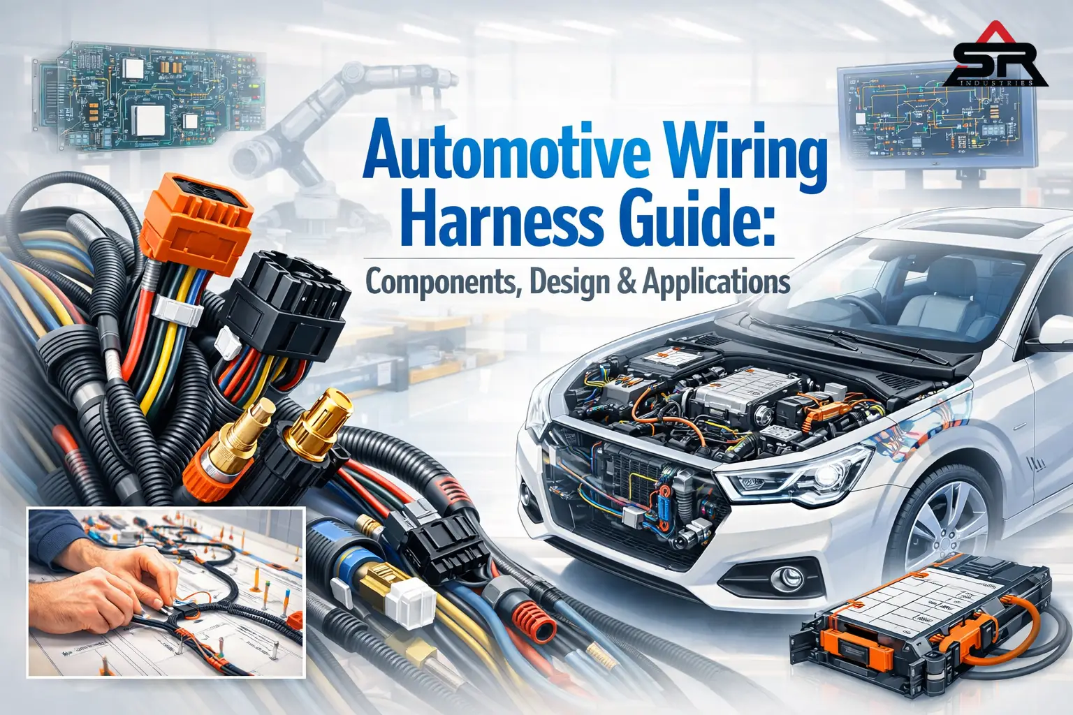
An automotive wiring harness is a structured bundle of wires, connectors, and terminals that transmits electrical power and data across a vehicle. It ensures reliable communication between components like the engine, sensors, lights, and onboard computers while protecting circuits from heat, vibration, and moisture.
Most people think about horsepower. Engineers think about the wires.
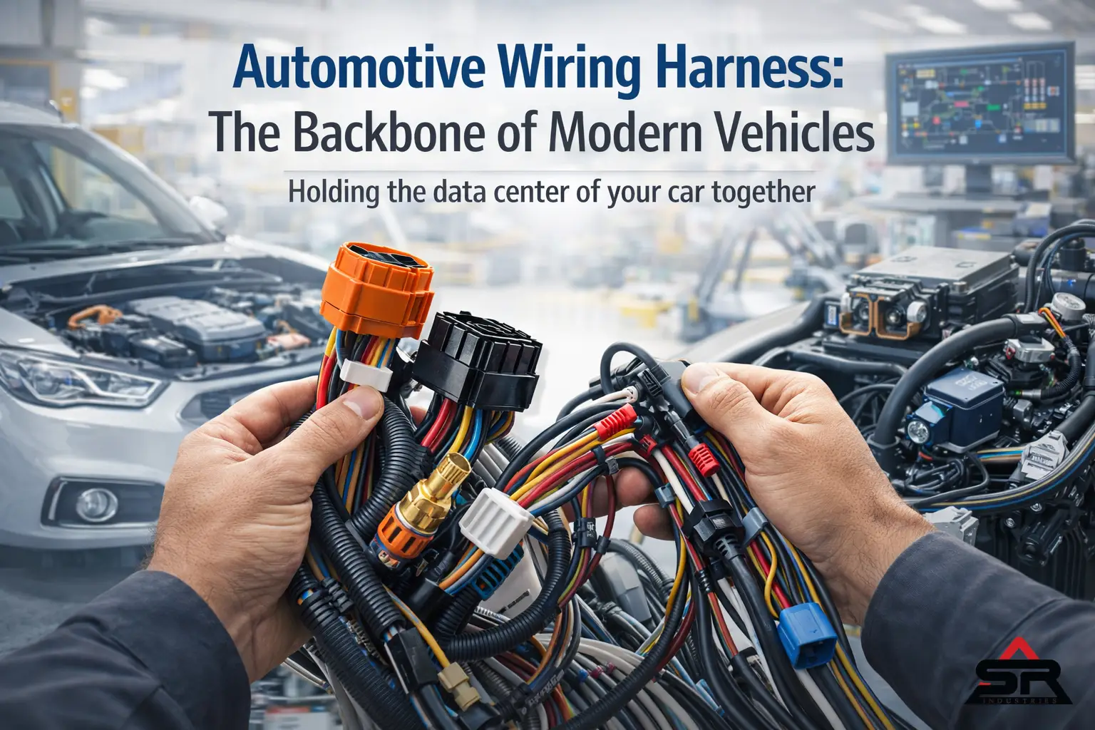
You can bolt the biggest turbocharger to an engine block, but if the sensor data drops for a millisecond, the engine runs lean and blows up. That is the reality of modern car manufacturing. A vehicle today is essentially a rolling data center wrapped in stamped sheet metal. And the physical infrastructure holding that data center together? The automotive wire harness design.
It is heavy. It is wildly expensive to manufacture. And it causes more warranty nightmares than almost any other component on the assembly line. Let’s break down exactly how these highly complex systems are engineered, why they fail, and how the shift to EVs is tearing up the entire automotive rulebook. This automotive wiring harness acts as the backbone of modern vehicles, ensuring seamless communication between critical components like sensors, ECUs, and power systems.
If you want to understand how wiring harness differs from cable assemblies, read our detailed guide on Wire Harness vs Cable Assembly.
Automotive Wiring Harness Components Explained (Complete Breakdown)
You cannot build a flawless electrical network without understanding the base materials. We aren’t just tying copper strings together. This is an exercise in extreme material science.
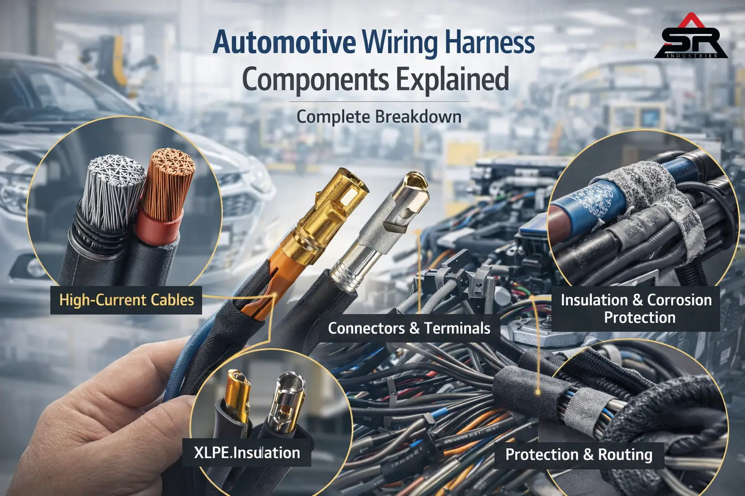
1. The Core Conductors (Wires and Cables)
Copper rules everything. But copper has a massive problem. Weight.
A standard luxury sedan carries over two miles of internal wiring. That copper adds up to 150 pounds of dead weight. For an automotive engineer trying to shave ounces off a chassis to meet strict emissions targets, that much copper is an absolute nightmare. Every car wiring harness is carefully engineered using specific materials and configurations to handle different electrical loads and environmental conditions.
So, what are the alternatives?
Aluminium. We are seeing a massive shift toward aluminium battery cables. Aluminium weighs significantly less than copper, but it comes with a severe engineering penalty. Aluminium expands and contracts under thermal load much faster than copper. If you crimp an aluminium wire the exact same way you crimp a copper one, the connection will eventually loosen. Resistance goes up. Heat builds up. Then, the connector melts entirely. To fix this, manufacturers use specialized ultrasonic welding and anti-corrosion pastes, proving that modern automotive wire harness design is a constant, brutal battle between saving weight and preventing thermal meltdowns.
Then we have the insulation. The plastic skin wrapped around the wire.
You cannot use standard PVC in an engine bay. It will literally melt. Instead, we specify XLPE (Cross-Linked Polyethylene). XLPE is chemically altered so its molecular bonds form a tight 3D grid. This means it can sit inches away from a 250-degree exhaust manifold and not turn to goo. It also resists motor oil, brake fluid, and battery acid. Inside the cabin, where temperatures remain stable, we switch back to thinner, cheaper PVC. Every penny counts when you build millions of cars a year, but compromising on that vehicle wiring harness insulation in the wrong zone will doom the entire electrical network.
2. Connectors and Terminals (The Synapses)
Wires are dumb. Terminals do the actual work. A terminal is the metal pin. The connector is the plastic shell holding it. The biggest enemy of a car wiring harness is not water. It is vibration.
Engines vibrate violently. Roads are bumpy. This causes a tiny, microscopic rubbing between the mated male and female terminals. We call this fretting. Every time those pins rub, they scrape off a microscopic layer of metal, exposing the raw material underneath to oxygen. It oxidizes.
This creates electrical resistance. Suddenly, your mass airflow sensor is reporting the wrong voltage back to the ECU. The car idles rough. The mechanic cannot figure out why, because the wire visually looks perfectly fine.
How do we stop fretting? Specific plating materials.
For high-power circuits—like the fuel pump or starter—we use tin-plated terminals. Tin is cheap. High voltage easily blasts right through the thin layer of oxidation that forms on tin. But for low-power data sensors? The voltage is too weak to push through that oxidation. We must use gold-plated terminals. Gold does not oxidize. Period. It guarantees a perfect signal, which is exactly why your critical airbag sensors rely on it.
3. Protection and Routing (Shielding the System)
You cannot run bare wires across sharp stamped steel. That is asking for a short circuit and a total car fire. The harness needs heavy armor.
Under the hood, we use high-temp split loom corrugated tubing. It is rigid, tough, and easily deflects flying gravel or dropped wrenches. But bring that split loom into the cabin, and you introduce a totally different problem: Noise.
Hard plastic tubing vibrating against a plastic dashboard sounds terrible. Customers hate it. To kill the noise (NVH – Noise, Vibration, Harshness), engineers wrap the cabin harnesses in soft PET fleece tape. It dampens the sound completely.
In areas where the harness must flex—like the rubber boot between the chassis and the driver’s door—we use braided nylon sleeving. That section of the vehicle wiring harness will bend hundreds of thousands of times over the car’s life. The sleeving prevents the internal copper wires from chafing against themselves and snapping.
Harness Component | Primary Material | Engineering Application | Environmental Challenge |
High-Current Cables | Stranded Copper / Aluminum | Main battery lines, starter motors | Weight reduction, extreme heat |
Sensor Terminals | Gold-Plated Brass | Airbag modules, ADAS cameras | Micro-vibration (Fretting), oxidation |
Engine Insulation | XLPE (Cross-Linked Polyethylene) | Engine compartment sensor routing | Chemical exposure, high temperatures |
Cabin Armor | PET Fleece Cloth Tape | Dashboard and interior routing | NVH (Noise & Vibration) reduction |
Expert Pro-Tip: Never pierce the insulation of a wire with a sharp test probe to check for voltage. You are creating a microscopic entry point for moisture. In two years, capillary action will draw water three feet down that wire, completely corroding it from the inside out. Always back-probe the connector housing instead.
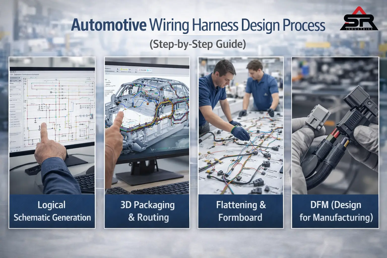
Automotive Wiring Harness Design Process (Step-by-Step Guide)
How does a giant spool of copper actually become a finished product? It is a grueling, complex process. Automotive wire harness design requires merging advanced digital simulation with intense physical, manual labor. It is one of the few areas in auto manufacturing where robots haven’t completely taken over.
Step 1: Logical Schematic Generation
Before anyone cuts a physical wire, electrical engineers build a logical map.
Think of it like a subway map. It shows you exactly which stations connect, but it doesn’t show you the actual physical shape of the tunnels. We use software like Siemens Capital to define the electrical rules. If a heated seat draws 15 amps, the software automatically calculates the required wire gauge to prevent the voltage from dropping over a 10-foot run. It tells us exactly which fuse size to specify. This logical schematic is the mathematical foundation of the entire car electrical system wiring.
Step 2: 3D Packaging and Routing
Now the mechanical engineers take over. They take the logical “subway map” and force it into the real-world 3D CAD model of the car chassis.
This is brutally hard. Space is incredibly tight. We have strict keep-out zones. You cannot route a wire within 50 millimeters of the exhaust piping. The radiant heat will cook the XLPE insulation. We have tight bend radius rules. A thick 2/0 gauge battery cable is incredibly stiff. You cannot bend it at a sharp 90-degree angle to get around a suspension strut. The copper strands inside will snap. We have to design long, sweeping curves.
And we have to worry about pinch points. When the car goes down the assembly line, a worker is going to shove that harness through a tight hole in the metal firewall. If we don’t design a heavy-duty rubber grommet exactly at that location, the sharp sheet metal will slice right through the bundle. Efficient routing is essential to ensure that the vehicle wiring harness performs reliably without exposure to heat, sharp edges, or mechanical stress.
Step 3: Flattening and the Formboard
You cannot build a flexible wire assembly in a 3D digital space. You need a physical guide.
The software mathematically “flattens” the 3D CAD model into a 2D drawing, completely to scale. We print this massive drawing out—sometimes it’s 15 feet long—and glue it to a wooden board. This is the formboard. We hammer wooden pegs into the board at every branch and junction point. Then, human workers physically lay the wires onto the board, routing them around the pegs exactly as the schematic dictates.
Step 4: DFM (Design for Manufacturing)
This is where the actual money is made or lost.
Because wires are floppy, robots are terrible at picking them up and routing them. Building a car wiring harness is almost entirely manual labor. If an engineer designs a harness with two large connectors too close together, the worker’s hands literally won’t fit to wrap the tape around the junction. The assembly line slows down. Costs skyrocket.
Good DFM means designing the harness so a human can build it quickly, ergonomically, and without making errors. If the design is bad, the automotive wiring harness manufacturer will reject it entirely or charge a massive premium.
Expert Pro-Tip: Color-coding is an underrated DFM tool. Never use two connectors with the exact same pin count and the same color plastic near each other on a branch. A tired assembly line worker will eventually plug the window switch connector into the door lock module. Make one black and one gray, and physically key them differently so they cannot be cross-plugged under any circumstances.
The EV Revolution: Redefining the Wiring Harness for EV Cars
Combustion cars are complicated. Electric vehicles are a completely different beast entirely. The shift to EVs didn’t just change the engine; it blew up the entire vehicle wiring system architecture. We are no longer dealing with simple 12-volt circuits. We are dealing with lethal electrical power. In electric vehicles, the automotive wiring harness must handle significantly higher voltages and complex data transmission requirements.
High-Voltage vs. Low-Voltage Networks
An EV has two distinct nervous systems running parallel to each other.
First, you have the traditional 12V system. This runs the radio, the wipers, and the window motors. Second, you have the High-Voltage (HV) traction system. This runs at 400 volts, 800 volts, or even higher. It moves massive amounts of current directly from the battery pack to the electric motors.
This introduces a terrifying problem: Electromagnetic Interference (EMI).
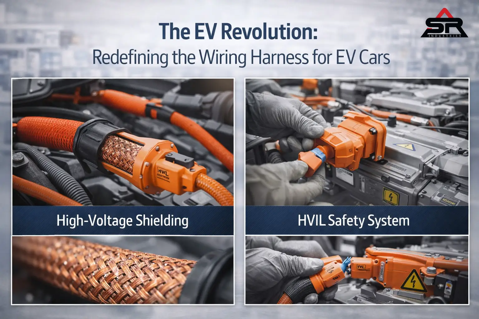
When you push 400 amps through a thick cable, it generates a massive, invisible magnetic field. If that high-voltage cable runs too close to a low-voltage sensor wire, that magnetic field will induce a rogue electrical current in the small wire. It will completely scramble the data. Suddenly, the car’s computer thinks the brake pedal is pressed when it isn’t. To stop this, EV high-voltage cables use heavy, braided metal shielding to trap the magnetic field tightly inside the cable. Advanced shielding techniques are now a standard part of EV automotive wire harness design to prevent signal interference.
Thermal Overload and Active Cooling
High current creates heat. It is basic physics.
During extreme track acceleration or DC fast charging, those HV cables get dangerously hot. If the insulation melts, you have a catastrophic fire. Some high-end performance EVs are now using actively cooled charging cables. They literally pump liquid coolant right through the center of the wiring harness to keep the copper from melting down.
The HVIL Safety Loop
Mechanics and first responders need absolute certainty they won’t be electrocuted when they cut into a wrecked EV.
By law, all high-voltage cables must be bright orange. But we go a step further. Every HV connector contains a High Voltage Interlock Loop (HVIL). It is a tiny, sacrificial low-voltage wire running through the main heavy-duty plug. If someone unplugs that connector, the tiny HVIL pin disconnects milliseconds before the massive high-voltage pins disconnect. When the computer senses the HVIL circuit is broken, it instantly fires internal contactors inside the main battery pack, shutting off all high voltage to the car. It happens faster than the blink of an eye. Safety innovations like HVIL are critical in modern vehicle wiring harness systems to protect both users and technicians.
System Specification | Traditional ICE Architecture | Modern EV Architecture | Safety Implication |
Operating Voltage | 12V to 14.4V | 400V, 800V, up to 1000V | High risk of lethal electrocution in EVs |
Cable Shielding | Minimal (Only on specific data lines) | Mandatory (Braided copper on all HV lines) | Prevents EMI from scrambling critical sensors |
Current Capacity | 100A peak (Starter motor) | 300A+ continuous (Traction motors) | Extreme thermal management required |
Connector Security | Standard mechanical plastic latch | HVIL (High Voltage Interlock Loop) | Instantly cuts main battery power if disconnected |
Applications of Automotive Wiring Harness in Modern Vehicles
A car does not have one giant, singular harness. That would be completely impossible to install on a fast-moving assembly line. Instead, the vehicle is broken down into specific modular zones. Each zone gets its own custom automotive wiring harness, and they all plug together at the very end of the line. Different types of automotive wiring harness systems are used across various parts of the vehicle depending on functionality and environment.
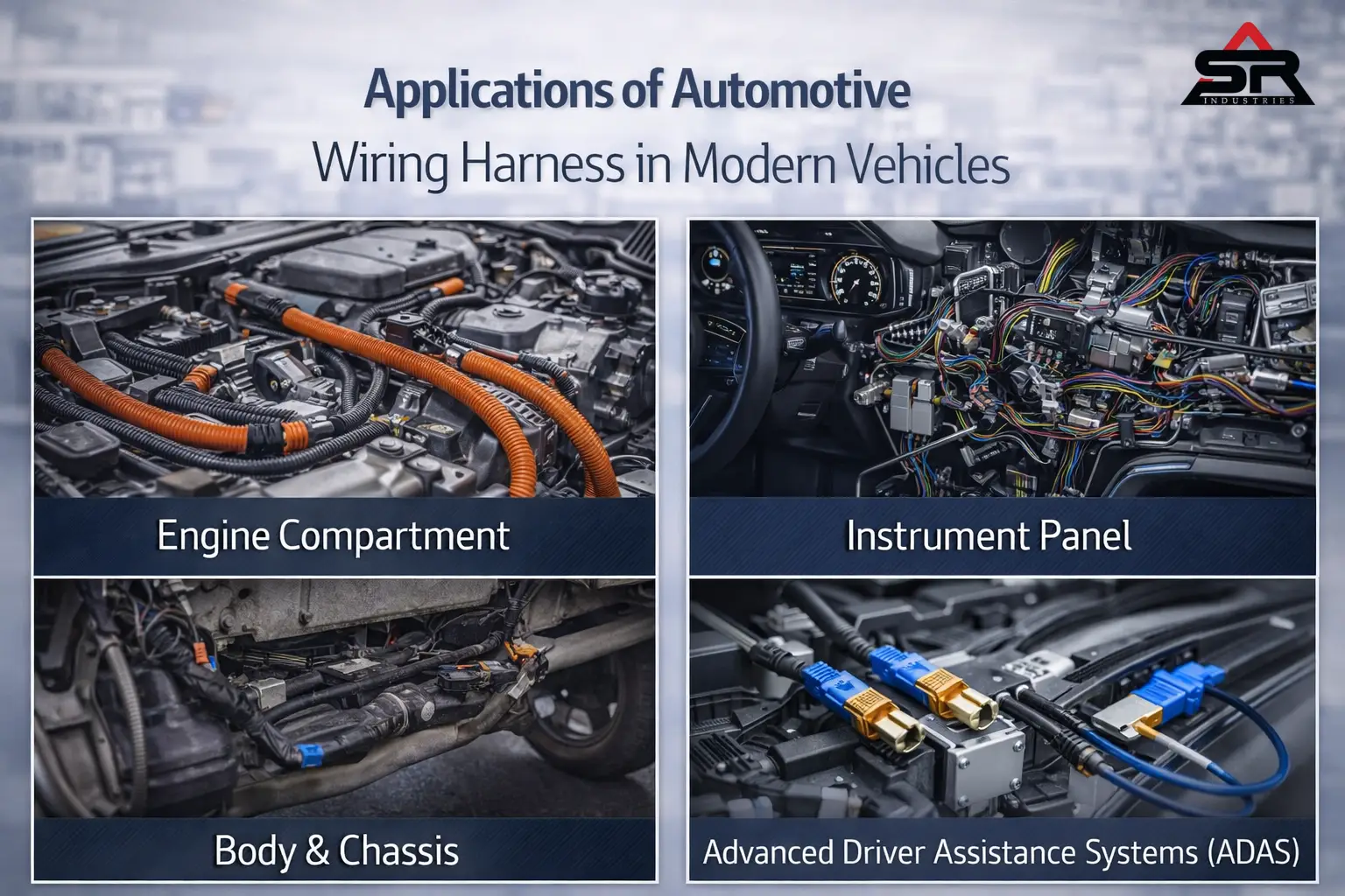
1. The Engine Compartment Harness
This is the survivor. It lives in the harshest environment on the planet.
It connects the Engine Control Unit (ECU) to the fuel injectors, the crank position sensor, the mass airflow sensor, and the ignition coils. It faces 250-degree heat, freezing winters, road salt, boiling motor oil, and constant, violent vibration. Materials here are non-negotiable. Only the highest-grade XLPE insulation and heavy-duty corrugated Armor will survive. The engine bay requires the most robust car wiring harness due to extreme heat and continuous vibration.
2. The Instrument Panel (Dashboard) Harness
Hidden right behind your steering wheel is an absolute nightmare of wires.
This harness controls the infotainment screen, the HVAC blower motor, the digital gauge cluster, and the interior ambient lighting. The primary engineering constraint here is physical space. Behind the dashboard, there is almost zero room. Engineers rely heavily on Ultra-Thin Wall (UTW) copper wire. By shaving tiny fractions of a millimeter off the plastic insulation of every single wire, the overall bundle becomes much smaller and drastically easier to cram behind the radio chassis. Compact automotive wiring harness layouts are essential in dashboards where space is extremely limited.
3. The Body and Chassis Harness
This is the longest harness in the car. It runs from the front fuse box all the way back to the rear taillights.
It manages the fuel pump, the power seats, the window regulators, and the ABS wheel speed sensors. Because it runs directly along the floorboards and under the car, it must be highly resistant to water ingress and physical crushing forces from road debris.
4. Advanced Driver Assistance Systems (ADAS)
This is the bleeding edge of the entire automotive industry.
Radar, LiDAR, and high-definition cameras cannot use standard copper wire. They generate way too much data. If you are relying on a front-facing camera to spot a pedestrian and slam on the emergency brakes, you cannot tolerate a single microsecond of lag. ADAS applications rely entirely on Automotive Ethernet and specialized FAKRA coaxial cables. They push gigabits of data per second. Routing these is incredibly difficult because coaxial cables cannot be bent sharply without completely ruining the data transmission signal. Modern vehicle wiring harness systems for ADAS rely on high-speed data transmission technologies instead of traditional wiring.
Sourcing: Finding a Reliable Automotive Wiring Harness Manufacturer
If you are an OEM or an EV startup, picking a car wiring harness supplier will literally make or break your production launch.
You cannot just sort by the cheapest price per unit. A cheap harness will result in ghost electrical gremlins that will completely tank your brand reputation. When you sign a supplier contract, you are paying for their quality control systems.
What exactly should you look for?
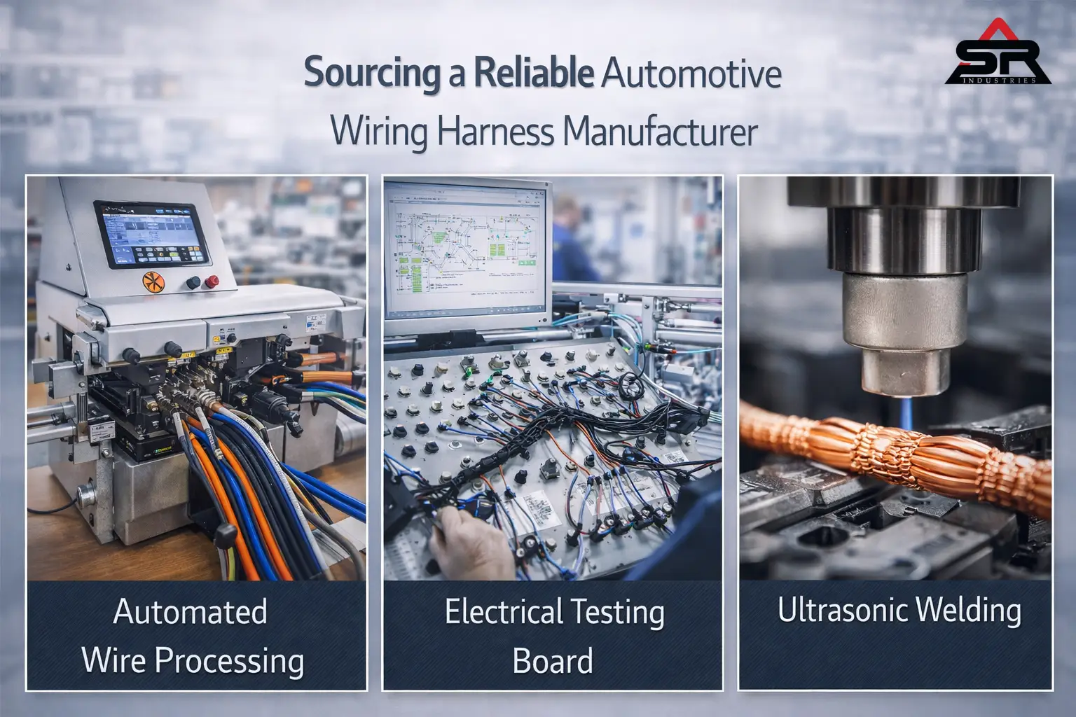
First, automated wire processing. Does the factory use high-end Schleuniger or Komax machines? These machines cut, strip, and crimp the terminals onto the wire. More importantly, they feature Crimp Force Monitoring (CFM). CFM measures the exact physical force of every single crimp in real-time. If the machine senses that a wire is missing even one tiny strand of copper, it immediately cuts the wire into pieces and throws it in the scrap bin. It completely removes human error from the equation.
Second, mandatory testing. 100% electrical testing is non-negotiable.
The finished harness must be plugged into a massive computerized test board before it ever leaves the factory. The computer sends a tiny voltage through every single pin. It verifies continuity—making sure pin A actually goes to pin B. It also checks for high resistance and microscopic short circuits. If the factory relies solely on humans visually looking at the harness, walk away immediately.
Finally, ask heavily about their splicing technology.
When two wires need to join together inside the harness, they are spliced. A cheap supplier will use a basic metal crimp band and wrap it in tape. That splice will eventually fail. A premium supplier uses ultrasonic welding. High-frequency sound waves physically melt the copper molecules of the two wires together, creating a solid, perfect joint with absolute zero electrical resistance.
Zonal Architecture: The End of the Traditional Harness
We are hitting a physical brick wall. As cars get smarter, we keep adding more wires. The harnesses are getting too thick, too heavy, and too rigid for workers to easily install. We cannot just keep making the bundles bigger. Zonal architecture is transforming traditional automotive wiring harness systems into more efficient and lightweight networks.
The solution is Zonal Architecture. Instead of running fifty individual wires from the headlights all the way back to a main computer under the driver’s seat, we decentralize the system. We place small, highly powerful “Zone Controllers” in the four corners of the car. The front-left headlights, radar, and crash sensors plug directly into the front-left zone controller using very short wires.
Then, the four zone controllers talk to the main central computer via a single, ultra-high-speed Automotive Ethernet cable.
Think of it exactly like a computer network in an office building. You don’t run a separate cable from every single keyboard directly to the main server. You plug them into local switches, and the switches talk to the server. This drastically cuts the overall weight. It reduces manufacturing complexity. It slashes costs. And it provides the massive data bandwidth required for fully autonomous, self-driving vehicles. The traditional, massive copper bundle is dying. High-speed networking is taking over. This shift is redefining the future of automotive wire harness design, focusing on scalability, speed, and reduced complexity.
Mastering how an automotive wiring harness works means understanding the tight intersection of mechanical stress, electrical theory, and brutal real-world environments. We aren’t just tying wires together. We are engineering the nervous system of complex, multi-ton machines operating at high speeds. From battling microscopic fretting corrosion on gold-plated terminals to managing the lethal magnetic fields of 800-volt EV cables, the discipline requires absolute precision. The shift toward zonal architecture and high-speed data networks is accelerating rapidly. The companies that adapt to these lightweight, modular electrical systems will dominate the next decade of manufacturing. The rest will simply be left dealing with the warranty claims of the past.
Frequently Asked Questions (FAQ)
Q. How do you determine the correct wire gauge for a vehicle wiring harness?
A: Wire gauge is strictly calculated based on the maximum current draw (Amperage) of the component and the total length of the wire run. High-current devices like starter motors require thick, low-gauge wire (like 2 or 4 AWG) to prevent overheating and severe voltage drops, while low-draw sensors use thin 20 or 22 AWG wire.
Q2. What is the difference between CAN bus and standard electrical wiring in cars?
A: Standard wiring transmits simple electrical power (on/off voltage) to activate devices like lightbulbs or motors. A CAN bus (Controller Area Network) uses a twisted pair of wires to transmit complex digital data messages, allowing multiple computers and sensors to communicate with each other over a single shared network, drastically reducing the total number of wires needed.
Q3. Why is cross-linked polyethylene (XLPE) used in engine compartments?
A: XLPE is chemically processed to create a three-dimensional molecular bond that makes it highly resistant to extreme temperatures and corrosive automotive fluids. Unlike standard PVC, which will melt near exhaust manifolds or degrade when exposed to motor oil, XLPE maintains its structural and insulating integrity under severe under-hood conditions.
Q4. How does a High Voltage Interlock Loop (HVIL) protect mechanics?
A: An HVIL is a continuous low-voltage safety circuit routed through all high-voltage connectors in an EV. If a technician attempts to unplug a high-voltage cable, the shorter HVIL pins break contact first, instantly commanding the battery’s internal contactors to open and cut off the lethal high-voltage power before the main pins fully separate.
Q5. Can an automotive wiring harness be spliced if a wire breaks?
A: Yes, but it must be done with extreme care. You cannot use household twist-on wire nuts. A broken automotive wire should be repaired using uninsulated butt connectors, properly crimped with specialized ratcheting tools, and completely sealed with dual-wall, adhesive-lined heat shrink tubing to completely block out moisture and prevent future corrosion.