
Why Power Cord Quality Matters: Safety, Performance & Reliability
How Wire Harnesses Power Modern Industries: A Complete Guide for OEMs
Walk onto any high-volume manufacturing floor, and you’ll quickly spot the silent killer of profit margins: point-to-point wiring. As OEM assembly lines scale, hand-routing individual cables across a machine chassis isn’t just a slow drain on resources—it’s an open invitation for human error.
A custom-engineered wire harness solves this by consolidating complex electrical routing into a single, pre-tested, drop-in unit. This guide strips down the actual mechanics of industrial wire harnesses, bypasses the generic procurement advice, and looks at why custom engineering is the only viable path for true production at scale.
The Engineering Gap: Why Off-the-Shelf Wiring Fails OEMs
Go to a supplier, buy a spool of 18 AWG copper, and start cutting. It sounds cheap. It’s actually the most expensive mistake an engineering team can make.
When you buy generic lengths of pre-terminated cables, you guarantee failure. Why? Because you end up with service loops. A service loop is that extra six inches of slack wire you have to aggressively zip-tie and stuff into a corner of your enclosure.
That slack adds unnecessary weight. It acts as an antenna for electromagnetic interference (EMI). In high-vibration environments, that heavy bundle of slack swings, creating mechanical stress right at the connector joint. Eventually, the mechanical stress transfers to the connector joint, the crimp fractures, and an entire assembly line halts over a $0.10 component.
Moving to a custom 3D-routed harness eliminates this guesswork. Instead of workers measuring and cutting on the fly, they take a pre-validated harness, snap it into pre-defined chassis clips, and click the connectors home. In practical application, we consistently see OEMs drop three hours of tedious hand-wiring down to a sub-five-minute installation.
Anatomy of a True Industrial Wire Harness
A harness is a system. It is only as strong as its weakest component. To specify a reliable build, you need to understand exactly what you are asking your supplier to assemble.
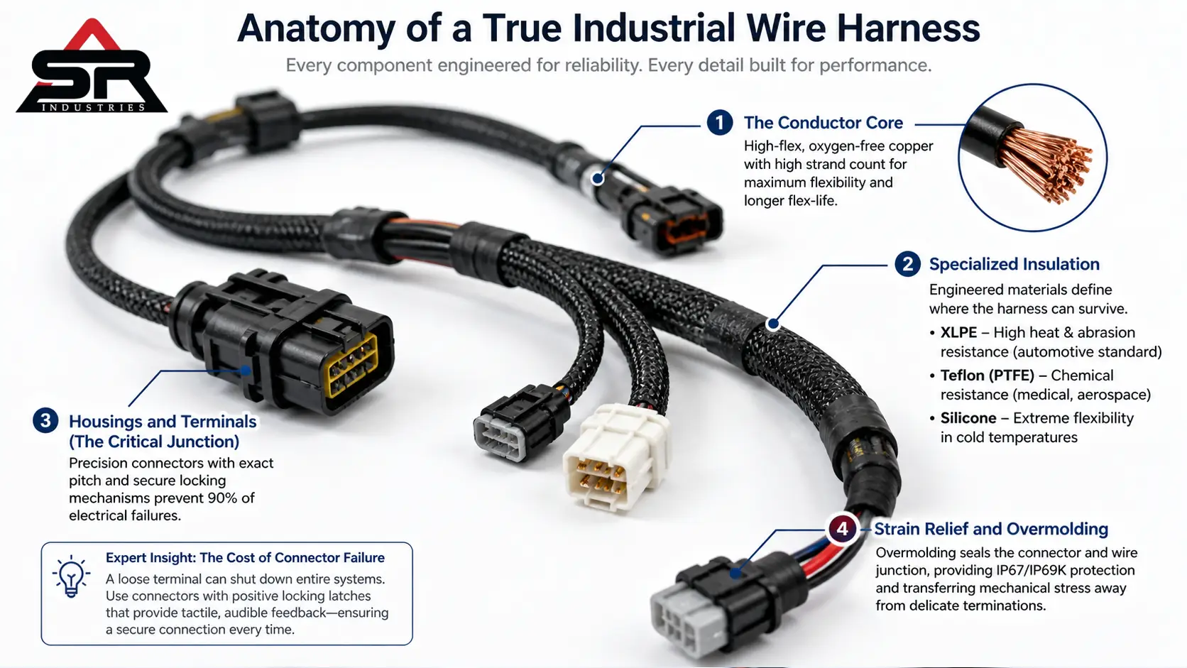
1. The Conductor Core
The actual wire. Standard copper is fine for static environments. But if this harness is going into a robotic arm that articulates 5,000 times a shift? Standard copper snaps. You need high-flex, oxygen-free copper with a high strand count. More individual strands equal higher flexibility and a longer flex-life before metal fatigue sets in.
2. Specialized Insulation
PVC is cheap. It works for a desk lamp. Do not put it near an industrial boiler.
Insulation and shielding materials define where the harness can survive.
- XLPE (Cross-linked Polyethylene): Handles high heat and severe abrasion. The standard for automotive engine bays.
- Teflon (PTFE): Impervious to most chemicals. Used heavily in medical devices and aerospace.
- Silicone: Extreme flexibility at freezing temperatures.
3. Housings and Terminals (The Critical Junction)
This is where 90% of electrical failures occur. Connectors are not generic. You are specifying exact pitch measurements and locking mechanisms. A poorly specified connector rattles loose.
Expert Insight: The Cost of Connector Failure When integrating precision industrial equipment, the physical connection dictates the reliability of the entire machine. Take complex fluid control systems utilizing Uflow solenoid valves, or heavy-duty monitoring setups using WIKA pressure transmitters. A loose terminal inside a Uflow manifold doesn’t just trigger an isolated error code—it risks shutting down an entire processing pipeline. To prevent this, specifiers must demand connectors with positive locking latches that provide tactile, audible feedback to the assembly worker.
4. Strain Relief and Overmolding
Wires bend. Terminals shouldn’t. If a wire bends right where it meets the metal terminal, the copper strands break. Overmolding is a process where the entire connector and the first few inches of the wire are injected with a hot polymer, sealing it completely. It provides absolute waterproof protection (IP67 or IP69K) and transfers all mechanical pulling stress away from the delicate internal solder or crimp joints.
Cable Harness vs Wire Harness: Clearing the Confusion
Stop letting your procurement team use these words interchangeably. They are completely different products with different cost structures.
A wire is a single conductor. A cable is multiple wires wrapped together in a single jacket. Therefore, the assemblies serve different masters.
Specification | The Wire Harness | The Cable Harness / Assembly |
Structure | Individual insulated wires held together by zip ties, lacing cord, or a thin protective sleeve. | Multiple wires permanently encased inside a thick, heavy-duty extruded polymer jacket. |
Application Environment | Protected. Meant to live inside an enclosure, dashboard, or machine chassis. | Exposed. Built to survive outdoor weather, foot traffic, or heavy machinery rolling over it. |
Maneuverability | High. You can easily break out individual wires at any point along the run to route to different sensors. | Low. It is stiff. Breaking out individual wires requires stripping back the heavy outer jacket, compromising the seal. |
Cost Implication | Lower material cost, higher manual labor for routing and tying. | Higher material cost due to the heavy jacketing extrusion process. |
Deep Dive: Industry-Specific Harness Requirements
You cannot take a harness designed for a server rack and put it in a tractor. The environment dictates the engineering.
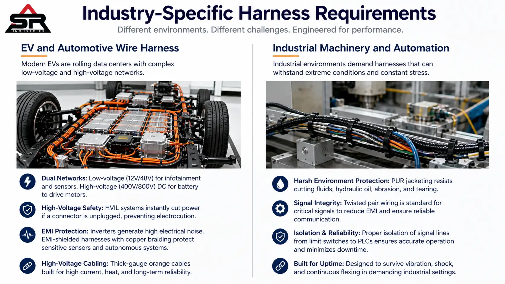
The EV and Automotive Wire Harness
The automotive industry consumes more wire than almost anyone else. A modern electric vehicle is a rolling data center.
Wire harness design for EV systems is currently the most difficult engineering challenge in the sector. You are dealing with two completely separate networks. You have the low-voltage (12V/48V) network running the infotainment and sensors. Then you have the high-voltage (400V/800V) DC network running from the battery pack to the drive motors.
These high-voltage lines require massive, thick-gauge orange cables. They also require high-voltage interlock loop (HVIL) systems. If a mechanic unplugs a connector without properly discharging the system, the HVIL instantly cuts the power to prevent electrocution. Furthermore, EV inverters create massive electrical noise. EMI shielded wire harness applications are mandatory here. Copper braiding must wrap the data lines to stop inverter noise from blinding the vehicle’s autonomous driving sensors.
Industrial Machinery and Automation
Factories are hostile environments. Wiring systems for machinery face constant threats from cutting fluids, hydraulic oil, and extreme mechanical shock.
A wire harness for industrial automation systems often requires polyurethane (PUR) jacketing. PUR is highly resistant to industrial oils and physical tearing. If you are wiring a CNC machine, the signal lines running from the limit switches back to the PLC (Programmable Logic Controller) must be isolated. Twisted pair wiring is standard here. Twisting the wires together forces external magnetic fields to cancel themselves out, preserving the integrity of the data signal.
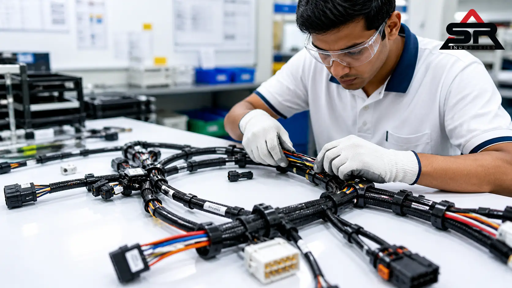
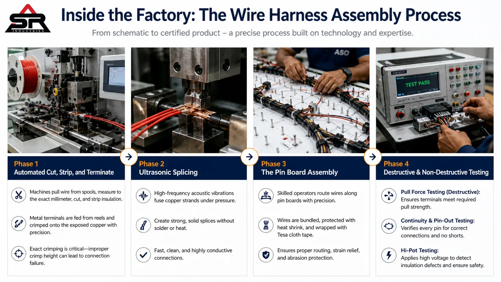
Inside the Factory: The Wire Harness Assembly Process
How does a schematic become a physical product? It requires a mix of highly advanced robotics and skilled manual labor. Complete automation is impossible. Wires are limp and flexible; robots struggle to route them through complex 3D paths.
Here is how top-tier wire harness manufacturers India and globally actually build your product.
Phase 1: Automated Cut, Strip, and Terminate
Raw wire arrives on massive spools. It is fed into automated processing machines (often from brands like Komax or Schleuniger). These machines pull the wire, measure it to the exact millimeter, slice it, and strip the insulation off the ends.
In the same fraction of a second, the machine feeds a metal terminal off a reel and crushes it onto the exposed copper. This is crimping. It is an exact science. The tooling dies must perfectly match the terminal. If the crimp height is off by a fraction of a millimeter, the connection will fail.
Phase 2: Ultrasonic Splicing
Sometimes, one wire needs to split into three. Traditional soldering is slow and leaves a brittle joint. Modern facilities use ultrasonic welding. High-frequency acoustic vibrations are applied to the copper strands under pressure, fusing them together into a solid nugget of metal without any solder or external heat. It is fast, clean, and highly conductive.
Phase 3: The Pin Board Assembly
This is where the humans take over. The manufacturer creates a physical, full-scale wooden or metal template of your harness, called a pin board or form board. It is covered in routing pegs and test fixtures.
Workers take the individual cut-and-crimped wires and route them manually along the board. They bundle the branches. They apply the heat shrink tubing. They wrap the entire main trunk in specialized Tesa cloth tape to prevent abrasion.
Phase 4: Destructive and Non-Destructive Testing
A harness doesn’t ship until it proves it works.
- Pull Force Testing (Destructive): A machine clamps onto the terminal and pulls until it rips off the wire. If the terminal fails before the specified pound-force rating, the entire crimping machine is halted and recalibrated.
- Continuity and Pin-Out Testing: The completed harness is plugged into a computerized test bench. It sends a low-voltage signal through every single pin to ensure there are no crossed wires.
- Hi-Pot Testing: For high-voltage applications, the test bench blasts the harness with a massive voltage spike. If the insulation has even a microscopic pinhole, the electricity will arc to an adjacent wire, and the bench will instantly fail the part.
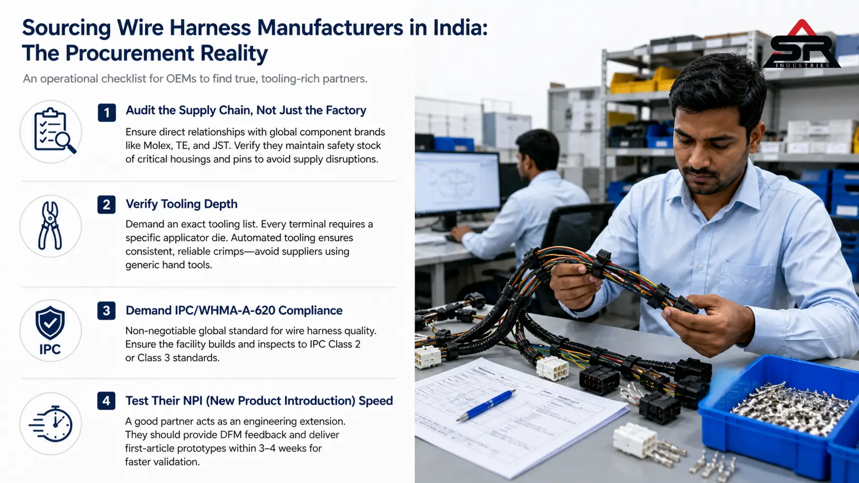
The Procurement Reality: Sourcing Wire Harness Manufacturers in India
The global supply chain realignment is no longer a secret. OEMs are actively derisking by moving away from single-source reliance, and India has rapidly emerged as a highly capable alternative for electrical components.
However, navigating the vendor landscape—whether you are vetting industrial cable harness manufacturers in Noida, exploring automation specialists in Pune, or sourcing from Chennai—requires an aggressive audit process. You aren’t just buying a wire; you are integrating a critical sub-assembly. Here is the operational checklist to filter out the middlemen and find true, tooling-rich manufacturing partners in India.
1. Audit the Supply Chain, Not Just the Factory
A wiring assembly requires parts from dozens of different global vendors. You need Molex connectors, Alpha Wire cables, and TE terminals. Ask the supplier directly: “How do you source your components?”
If they buy exclusively from spot-market distributors, walk away. When the global supply chain tightens, they will run out of parts, and your assembly line will stop. You want a manufacturer with direct, franchised relationships with the major connector brands. They should carry massive safety stocks of common housings and pins.
2. Verify Tooling Depth
Remember the crimping phase? Every single terminal type on the planet requires a specific, expensive steel applicator die to crimp it correctly. If you design a harness using a rare JST connector, the manufacturer must buy that specific tool.
If they don’t want to spend the money, bad suppliers will use a “generic” hand-crimper. It will look fine to the naked eye. It will fail in the field. How to choose wire harness manufacturer partners comes down to demanding their exact tooling list. If they don’t have the automated dies for your specified pins, they aren’t the right fit.
3. Demand IPC/WHMA-A-620 Compliance
This is non-negotiable. This standard is the global bible for cable and wire harness assembly. It defines exactly what an acceptable crimp looks like, how much solder is allowed on a joint, and how strain relief must be applied. If a facility in Pune or Noida is not building and inspecting to IPC Class 2 or Class 3 standards, do not put their products in your machinery.
4. Test Their NPI (New Product Introduction) Speed
Your engineers will make mistakes on the CAD drawings. It happens. A great supplier acts as a secondary engineering filter. Before they build, their internal DFM (Design for Manufacturability) team should review your schematics, catch the impossible bend radii, and suggest cheaper, equivalent connectors to lower your BOM (Bill of Materials) cost. They should be able to turn around a physical, first-article prototype within three to four weeks for your mechanical fitment checks.
Final Thoughts on Scaling Your Hardware
Wiring is not an afterthought. It is the central nervous system of your product. Treating electrical connectivity as a last-minute detail guarantees pinched cables, intermittent faults, and frustrated end-users.
By designing the routing concurrently with the mechanical chassis, standardizing your connector choices, and partnering with verified, tooling-rich manufacturers, OEMs can slash assembly times and drastically increase hardware reliability. Build it custom. Test it rigorously. Scale your production.
Technical FAQs for OEM Procurement
Q1. What is the standard lead time for a custom wire harness prototype?
For a manufacturer with a robust supply chain, a functional prototype typically takes 3 to 4 weeks. This timeline is heavily dependent on component availability; if your design specifies highly specialized or globally backordered connectors, prototyping can extend past 8 weeks.
Q2. How do you prevent wire harnesses from chafing and shorting out?
Chafing is prevented through physical barriers and smart routing. Engineers use corrugated plastic looming, braided fiberglass sleeving, or heavy Tesa tape over the wire bundles. Additionally, the harness must be secured to the chassis using P-clamps or edge clips every few inches to prevent it from swinging and rubbing against sharp metal edges during vibration.
Q3. Why do manufacturers require a minimum order quantity (MOQ) for harnesses?
Setting up the automated cut-and-strip machines and loading the specific heavy steel crimping dies takes significant time and labor. To amortize the cost of this setup time, manufacturers require an MOQ. Building 10 harnesses costs almost as much in labor setup as building 500.
Q4. What is the difference between IPC Class 2 and IPC Class 3 wiring?
IPC Class 2 is the standard for dedicated service electronic products—equipment where high performance and extended life are required, and uninterrupted service is desired but not critical. IPC Class 3 is for high-performance harsh environment electronic products—where equipment downtime cannot be tolerated, and the equipment must function when required, such as in life support systems or aerospace.
Q5. Can a wire harness transmit both power and data simultaneously?
Yes, but it requires careful design. Running high-voltage power lines directly next to delicate low-voltage data sensors can cause electromagnetic interference, corrupting the data. To do this safely within a single harness, the data lines must be heavily shielded (usually with copper braiding or foil) and ideally separated by physical distance or insulation layers within the bundle.