
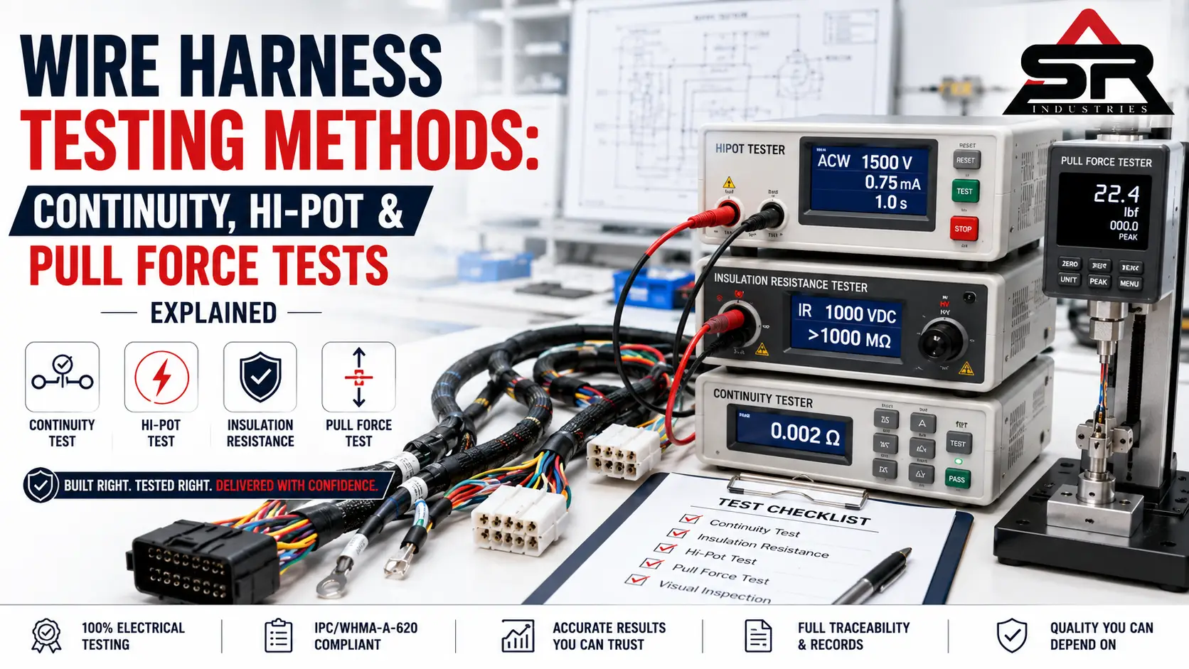
Wire Harness Testing Methods: Continuity, Hi-Pot & IPC-620
Answer Capsule: The core wire harness testing methods are continuity, dielectric withstand (hi-pot), insulation resistance, and crimp pull-force testing, backed by visual and dimensional inspection. Run them in sequence: continuity first to verify the circuit path, then insulation resistance and hi-pot to prove the dielectric system, with destructive pull testing on a sampling plan to validate crimp integrity.
A harness can pass a visual inspection and still fail in the field. These are the tests that catch what the eye cannot.
Quality engineers live by a simple cost progression: the 1-10-100-1000 rule. A defect caught at the test station costs roughly one unit of effort — a re-crimp, a re-test. Let it reach the customer’s incoming inspection and it costs ten. Let it reach their assembly line and it costs a hundred: line stoppage, containment, charge-back. Let it reach the field — inside a vehicle, a solar string, a battery pack — and the number jumps to a thousand or worse, because now it carries warranty, recall, and safety weight. Every test described below exists to keep the defect on the left side of that curve.
The trap is that the most expensive defects are the quietest ones. A crimp that looks textbook-perfect can pull apart under vibration. Two circuits that read “connected” on a handheld meter can arc through a thinned insulation wall the moment they see operating voltage. A terminal seated flush in its housing can still carry a build error introduced three stations upstream. Knowing how to test a wire harness properly means understanding that no single check is sufficient — each test is blind to the failure modes the others are built to catch.
Why Wire Harness Testing Is a Release Gate, Not a Formality
A mid-complexity automotive or industrial harness hides a high count of failure opportunities behind a simple-looking shape: dozens of circuits, hundreds of crimps, several connector housings, meters of routed and bundled cable. Each is a place where a missed strand, a backed-out terminal, a transposed wire, or a nicked jacket can hide.
Serious suppliers treat wire harness quality testing as the gate that releases the product — the harness ships because it was proven, not because it was built. For a procurement or supplier-quality engineer auditing a vendor, “do you test?” is a useless question; every supplier says yes. The questions that separate real capability from marketing are sharper: What is the test method? What is the acceptance limit, and where does it come from? Show the record for this batch. The sections that follow are what good answers look like.
Continuity Testing — Beyond Simple Go/No-Go
Run continuity first. It is the foundational electrical test and the highest-volume catcher of everyday build errors — opens, shorts, mis-wires, and the high-resistance joints that conduct but shouldn’t.
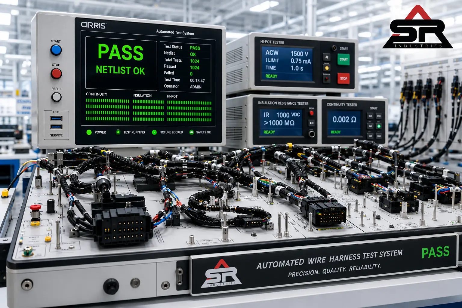
The basic version is a go/no-go check: apply a small current across each defined circuit, confirm low resistance on the intended path and infinite resistance everywhere else. On any real production volume, this runs on an automated harness test board — the harness plugs into a fixture that mirrors every connector, and the system verifies the full netlist against a stored master in a second or two. Industry-standard platforms like Cirris, CableEye from CAMI Research, and purpose-built Dynalab test boards handle this netlist verification across hundreds of points without the fatigue and probe-slip that drag down manual checking on high circuit-count assemblies.
Here is where generic guides stop and engineering begins. A simple two-wire continuity test answers “is it connected?” — but for signal-sensitive B2B circuits, connected is not the same as good. A crimp with marginal contact, partial strand engagement, or early oxidation will still pass a basic continuity threshold while its micro-ohm contact resistance quietly climbs. On a power circuit that extra resistance becomes heat. On a low-level sensor or data line it becomes signal degradation and intermittent faults that no one can reproduce on the bench.
That is why critical circuits get a four-wire Kelvin low-resistance measurement, not just a pass/open verdict. A healthy crimp contact typically sits in the low single-digit milliohms. When that figure drifts past the limit set for the circuit — often somewhere in the low tens of milliohms depending on the specification — the joint is flagged before it ever ships, even though a coarse continuity check would have waved it through. The threshold is where a harmless reading turns into a field-failure risk, and setting it correctly is a spec decision, not a default.
What continuity proves nothing about: whether the insulation between those correct circuits will survive being energised. That is the next gate.
Hi-Pot vs. Insulation Resistance — Two Tests, Two Jobs
These two get conflated constantly, and the confusion is expensive. They share a fixture and they both work across isolation barriers, but they answer opposite questions.
Dielectric Withstand (Hi-Pot): The Stress Gate
Hi-pot is a stress test with a pass/fail verdict. It applies a voltage far above the harness’s rated working level — anywhere from several hundred volts to a few kilovolts, AC or DC depending on the standard — between conductors that must stay isolated, and between conductors and shield or ground. The logic is deliberate brutality: if the insulation is going to break down, force it to break down here, under control, instead of in service.
The parameters that define a hi-pot screen are the test voltage, the dwell time (often one second on a production line, longer for qualification), and the leakage current threshold. While the high voltage is held, the instrument watches leakage in microamps to milliamps. Stay under the threshold and the insulation is holding — pass. A leakage spike, an arc, a flashover across a contaminated surface — fail. AC hi-pot stresses both polarities each cycle and exercises the insulation’s capacitive behaviour; DC hi-pot is gentler and makes leakage easier to read, but the harness must be discharged afterward because it holds charge.
Hi-pot is the test that catches the invisible: a thinned insulation wall, a micro-nick from a routing edge, contamination bridging two terminals, or inadequate creepage distance inside a connector housing. None of these show on continuity. All of them cause tracking, arcing, and shorts once the product sees full voltage.
Insulation Resistance: The Diagnostic Metric
Insulation resistance asks a gentler, quantitative question — not “will it survive a spike?” but “how good is the dielectric right now?” It applies a steady DC voltage, commonly 250 V to 1000 V DC, across the same barriers and measures the resulting resistance.
The output is a number, not a verdict, and that is the point. Healthy insulation reads very high — hundreds of megohms into the gigohm range. A low or sagging reading signals moisture ingress, contamination, or material degradation, and because it is a measurement it can be trended over time and across batches. Hi-pot proves the barrier is strong; insulation resistance proves it is clean and intact. Together they characterise the full dielectric system, which is why both are non-negotiable for harnesses heading into humid, high-voltage, or safety-critical duty — EV, solar, battery, where the insulation is the only thing between a live conductor and a hazard.
🔧 Shop Floor Insights
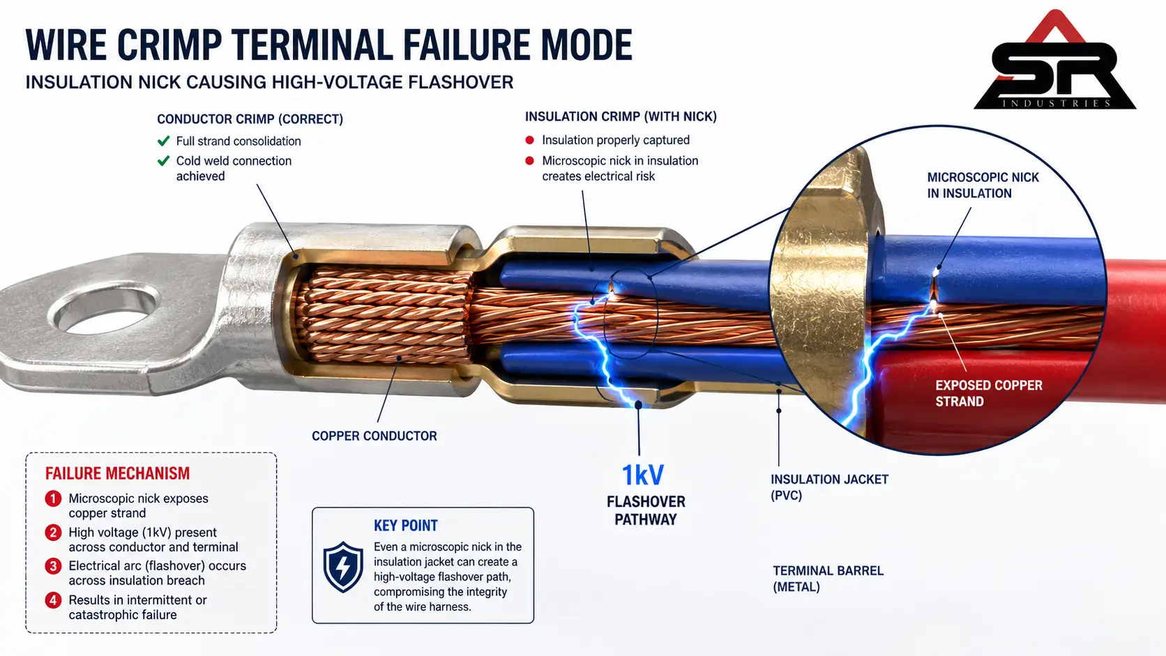
In our testing lab, the failure that catches buyers off guard most often is the terminal that sails through low-voltage continuity and then fails hard at 1 kV hi-pot. The circuit reads perfectly connected — low resistance, correct netlist — so on a continuity-only line it ships. But a micro-nick in the insulation near the conductor crimp, or a sliver of displaced insulation caught under the insulation crimp bellmouth, leaves a paper-thin gap that low voltage never notices.
Push 1,000 volts across that gap and it flashes over. We see the same story with strands fanned just outside the conductor barrel: continuity is happy, hi-pot is not. The lesson we hand every new operator is blunt — continuity tells you the wire goes where it should; only hi-pot tells you it stays insulated while doing it. A line that skips hi-pot is shipping these defects blind.
Pull Force & Crimp Testing (IPC/WHMA-A-620)
Electrical tests prove the harness works today. Pull-force testing proves the crimp will still be holding after the vibration, thermal cycling, and handling that service life delivers.
A crimp is a cold weld — the terminal barrel compressed onto the conductor to form one bond that is both electrical and mechanical. Too loose, it backs out or grows resistance. Too tight, it shears strands and goes brittle. Neither defect is visible, and — this is the part that matters — neither shows up on continuity. The crimp pull test is the only way that hidden mechanical quality gets a number.
The method is destructive and direct: clamp the terminal, pull the wire along its axis with a calibrated gauge, record the force needed to pull the conductor out of the crimp or break the wire, then compare it to a minimum. The reference for that minimum is IPC/WHMA-A-620, whose tables set a minimum crimp tensile force per wire gauge. Thicker wire holds more:
| Wire Size (AWG) | Indicative Minimum Pull Force |
|---|---|
| 30 | ~1.5 lbf (≈7 N) |
| 26 | ~3 lbf (≈13 N) |
| 24 | ~5 lbf (≈22 N) |
| 22 | ~8 lbf (≈36 N) |
| 20 | ~13 lbf (≈58 N) |
| 18 | ~20 lbf (≈89 N) |
| 16 | ~30 lbf (≈133 N) |
| 14 | ~50 lbf (≈222 N) |
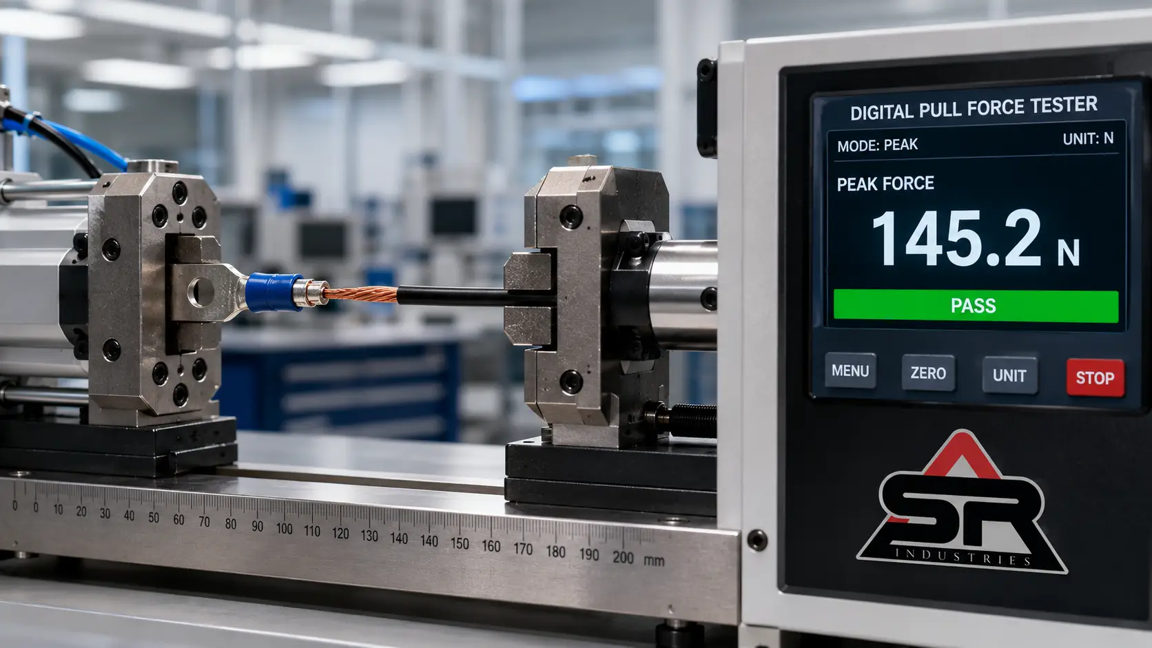
These figures are indicative — pull the exact minimum from the current revision of IPC/WHMA-A-620 Table 19-2 for the specific gauge and terminal in production, since the standard is periodically updated.
Expert note on why sampling is non-negotiable. Crimp quality degrades silently. A crimp press wanders out of spec gradually — die wear, a loosening setscrew, a fractionally drifting crimp height — and the cruel part is that crimp-press drift hides perfectly inside a clean continuity pass. The joint still conducts. The board still reports a good circuit. The only thing changing is mechanical pull-out strength, trending downward shift by shift while every electrical test stays green. Destructive pull sampling — a set number of crimps pulled per operator, per tool, per setup change — paired with crimp height validation is what surfaces that drift before it becomes a field failure. A downward trend in pull readings is usually the first sign a tool needs attention, and it shows up well before any harness actually breaks. Suppliers who trend this data catch tooling problems as tooling problems, not as warranty returns.
Visual & Dimensional Inspection
No instrument replaces a trained eye, and the IPC/WHMA-A-620 workmanship criteria are what that eye is calibrated against: correct crimp geometry, a proper bellmouth on the conductor barrel, clean strip length with no nicked or missing strands, full terminal seating, intact strain relief, correct tape, conduit, and labels.
Dimensional inspection confirms the harness is the right shape — overall and branch lengths, breakout positions, connector orientation — measured against the drawing, often on a formboard where the build is laid over a master pattern. A harness that is electrically flawless but 50 mm short, or branched the wrong way, will not install. Those defects pass every electrical test and still get rejected at the customer’s line. Run visual and dimensional checks around the electrical and mechanical tests, never instead of them.
Automated vs. Manual: Matching Method to Risk
Manual testing — a technician with a meter and a wiring schedule — is flexible and cheap to set up. It belongs on prototypes, very low volumes, and repair, where building a fixture would never pay back. Its weakness is the human factor: slow, fatiguing, and error-prone exactly when circuit counts are high and defects are most likely to slip.
Automated testing on a programmed test board verifies every circuit against a stored netlist in seconds and, on a combined tester, runs continuity, insulation resistance, and hi-pot in one sequence with a time-stamped record per unit. The advantages compound at volume — speed, repeatability, full coverage of every circuit on every unit — against the upfront cost of building and programming the fixture. The pattern most capable lines settle on: automated 100% electrical testing in production, manual methods reserved for prototype and rework, and destructive pull testing on a sampling plan regardless of which electrical method runs.
Test Records & Traceability (IATF 16949)
A test that is not recorded did not happen — not in any way a customer can verify. Under IATF 16949, the record is part of the product. Traceability means that for any shipped harness, the supplier can reconstruct the evidence: which program ran, what limits applied, the actual readings, the timestamp, the fixture, the pull-force log, the sampling plan, and the crimp-tool calibration status. When something goes wrong in the field, that record turns a vague failure into a bounded containment — this shift, this tool, these serials — instead of a blanket recall. For a buyer, retrievable test records are the proof of capability that no brochure can fake.
Pass/Fail Criteria Reference Table
The exact limits track the harness specification and the governing standard, but acceptance criteria are structured like this:
| Test | What it verifies | Typical Pass Condition | Typical Fail Condition | Recommended Setup |
|---|---|---|---|---|
| Continuity (go/no-go) | Correct circuit path | Resistance below limit (often less than 1 Ω) | Open, short, or mis-wire | Automated test board (netlist verification) |
| Low-resistance (4-wire Kelvin) | Contact resistance on critical circuits | Within milliohm limit (low single digits typical) | Reading above circuit-specific limit | Automated board with micro-ohm capability |
| Hi-Pot (dielectric withstand) | Insulation survives HV stress | Leakage below threshold for dwell; no breakdown | Arc, flashover, or excess leakage | Automated hi-pot tester (e.g. Cirris / CableEye class) |
| Insulation resistance | Dielectric health between circuits | Very high (hundreds of MΩ to GΩ) | Below specified minimum | Automated board (combined sequence) |
| Pull force / crimp | Mechanical crimp strength | Meets IPC/WHMA-A-620 minimum for gauge | Pulls out below minimum force | Manual/bench pull tester (destructive sampling) |
| Visual & dimensional | Workmanship and conformance | Meets A-620 criteria and drawing | Nicked strands, poor bellmouth, wrong length/routing | Manual inspection + formboard |
Use this as the framework, then pin the actual numbers to the product drawing and the applicable standard before testing starts.
Sequence Logic — Why Order Wins
The sequence is engineered, not arbitrary. Continuity first, because stress-testing the insulation of a mis-wired harness is wasted effort. Insulation resistance and hi-pot next, on the same electrical fixture, to characterise and then stress the dielectric. Pull testing in parallel on a sample basis, validating crimps and the tooling that makes them. Visual and dimensional inspection wrapped around the whole flow, since some checks come before electrical test and some after. Record everything as it happens.
That layered order is the line between a harness that was built and one that was proven. Each test sees a failure mode the others are blind to, and only the complete set closes the gaps.
FAQ: Wire Harness Testing
What is hi-pot testing?
Hi-pot (high-potential), or dielectric withstand testing, applies a voltage well above the harness's working level between conductors that should be isolated, holding it for a set dwell time while monitoring leakage current. Stay below the leakage threshold with no breakdown and the harness passes; arc or flashover and it fails. The test deliberately stresses the insulation on the bench to expose thin walls, micro-nicks, contamination, and inadequate creepage before the product is energised in service.
How is pull force measured?
Pull force is measured destructively with a calibrated tensile gauge. The terminal is held, the wire pulled along its axis, and the force to pull the conductor out of the crimp — or break the wire — is recorded and compared against the IPC/WHMA-A-620 minimum for that gauge. Because it destroys the sample, it runs on a sampling plan, and the data also confirms the crimp tooling is still in calibration.
Is every harness tested?
For non-destructive electrical tests — continuity, and usually hi-pot and insulation resistance — yes, on 100% of production units on capable lines, since they cover every harness without harm. Destructive pull testing runs on a defined sample per shift, operator, or tool change, because pulling a crimp apart destroys it. Visual inspection covers every unit; dimensional checks are full or sampled per the part and customer requirement.
Verify capability before you buy. Request the full test records — continuity, hi-pot, insulation resistance, and pull-force logs — and see the in-house testing lab and automated harness test board run a live sequence. Real capability shows up in the records, not the brochure.