
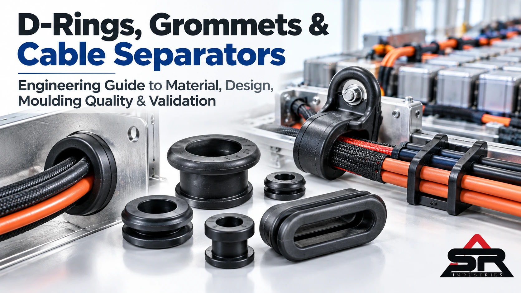
Rubber Grommets, D-Rings & Cable Separators: Engineering Guide
D-Rings, Grommets & Cable Separators: Engineering Guide to Material, Design, Moulding Quality & Validation
A rubber grommet, a D-ring or a cable separator is a small part sitting at a high-consequence interface. When one fails, the polymer is rarely the whole story. Far more often, the interface between the part, the panel, the cable, the environment and the installation process was never engineered as one system. The groove was sized on bare steel, the bore was sized on nominal cable diameter, the compound was specified by polymer family alone, or a parting line landed on the one surface that touches the cable jacket.
This guide is written for harness engineers, battery-pack and panel designers, quality engineers and the procurement teams who buy moulded cable accessories. It covers how each component works, which parameters drive its behaviour, where common specifications break down, and which values must be proven by validation rather than taken from a datasheet or a previous drawing. Wherever a number appears, the text states whether it comes from a standard, a material datasheet, or a worked example.
At a Glance: Which Component Solves Which Problem
A grommet protects a cable where it passes through an opening. A D-ring (a moulded retention loop) holds and guides a harness at a mounting point. A cable separator keeps conductors or bundles in controlled positions. A cell separator maintains spacing between battery cells and may contribute to the pack’s insulation system. Each component is chosen by the failure it must prevent, not by its appearance in a catalogue.
| Component | Main Function | Typical Mounting | Failure It Is Chosen to Prevent | Primary Validation |
|---|---|---|---|---|
| Rubber grommet | Edge protection, cable retention, sealing where designed for it[cite: 4] | Panel, bulkhead or enclosure opening[cite: 4] | Chafe-through at the hole edge; water or dust ingress[cite: 4] | Insertion and pull-out force; ingress test of the assembly[cite: 4] |
| Rubber D-ring / retention loop[cite: 4] | Retention and guidance of a harness[cite: 4] | Stud, fastener or chassis tab[cite: 4] | Harness sag, uncontrolled movement, wear against nearby parts[cite: 4] | Vibration and movement testing on the routed harness[cite: 4] |
| Cable separator[cite: 4] | Controlled spacing and layout[cite: 4] | Clipped to bundles, trays or supports[cite: 4] | Cable-to-cable abrasion; uncontrolled routing[cite: 4] | Fit, retention and environmental compatibility checks[cite: 4] |
| Cell separator / insulating spacer[cite: 4] | Mechanical spacing; possible contribution to insulation[cite: 4] | Between cells or within a cell holder[cite: 4] | Cell fretting, stack movement, loss of required electrical spacing[cite: 4] | Mechanical, electrical and, where relevant, thermal testing at module or pack level[cite: 4] |
Why Small Moulded Parts Create Large Failures
Cable damage at a pass-through tends to develop slowly. A burr on a punched hole or a fin of flash inside a bore contacts the jacket; vibration turns that contact into wear; the wear eventually exposes a conductor or opens a leak path. By the time an intermittent fault or a wet connector shows up, the grommet that started it may look almost undamaged to a casual inspection.
These failures are hard to catch at incoming inspection because the part is often dimensionally “in tolerance”. The problem lives in the combination: a correct part on an unexpectedly thick coated panel, a correct compound in contact with an incompatible cable jacket, a correct bore on a cable at the top of its diameter tolerance.
Four levels of evidence that must not be confused
One idea runs through the entire guide. The numbers used to approve a moulded cable accessory sit at four distinct levels, and a result at one level does not prove performance at the next
| Evidence level | What it describes | Examples | Typical source | What it cannot prove |
|---|---|---|---|---|
| Material property | Behaviour of a standard test specimen of a compound | Hardness (ASTM D2240), compression set (ASTM D395), fluid swell (ASTM D471), dielectric strength (ASTM D149), CTI (IEC 60112) | Compound datasheet or lab test | How a specific moulded shape behaves |
| Component property | Behaviour of the moulded part itself | Insertion force, pull-out force, bore dimensions, flash, dimensional stability after ageing | Part-level testing and inspection | Sealing or durability once installed in the real assembly |
| Assembly performance | Behaviour of part, panel and cable together | IP rating (IEC 60529), vibration durability, insulation resistance, dielectric withstand | Assembly testing | Whole-system safety or reliability |
| System performance | Behaviour of the vehicle, pack or equipment | Thermal propagation in a battery pack, harness field reliability, electrical safety approval | System testing and homologation, e.g. AIS-156 or AIS-038 Rev 2 for traction batteries in India | Nothing above it; this is the level approvals are granted at |
A compound with an excellent compression-set figure does not make a grommet IP67. A UL 94 flame classification of a material does not make a battery pack resistant to thermal propagation. A dielectric strength of 20 kV/mm on a test plaque does not give a separator a voltage rating. Keeping the four levels separate is the single most useful habit in specifying these parts.
How to Specify a Moulded Cable Accessory Without Guessing
The ten-step sequence below is a working framework for specifying grommets, D-rings and separators. Each step lists what goes in, what gets decided, what goes wrong when the step is skipped, and how the decision is checked.
| Step | Input | Engineering decision | Failure if ignored | Validation method |
|---|---|---|---|---|
| 1. Define the interface | Panel, stud, tray or cell holder; access for assembly | Grommet, D-ring, separator, or a combination | Wrong component type; sealing expected from a part never designed to seal | Design review against the function list |
| 2. Define cable and harness geometry | Cable OD and tolerance, jacket material, construction (shielded, braided), bundle size | Bore or loop size, number of passages | Loose bore on small cables, crushed jacket on large ones | Measurement of real cable samples across lots |
| 3. Define the environment | Temperature range, fluids, UV, ozone, humidity, contamination | Candidate compound families | Swelling, cracking, hardening, compression-set loss | Fluid immersion and heat ageing of candidate compounds |
| 4. Define mechanical movement | Vibration profile, angular movement, harness mass, service handling | Compliance level, support spacing, D-ring vs clamp | Fatigue, fretting at connectors, jacket wear | Vibration and articulation testing |
| 5. Define electrical requirements | Working voltage, transients, pollution degree, insulation type | Need for creepage ribs, CTI group, wall thickness | Tracking, breakdown, non-compliant spacing | Insulation-coordination review; withstand and insulation-resistance tests |
| 6. Select the compound | Steps 3 to 5 | Specific compound grade, not just polymer family | Right family, wrong grade | Datasheet review plus application-specific ageing |
| 7. Set the geometry | Panel data, cable data, compound stiffness | Groove, bore, flange, lips, radii, rib pitch | High insertion force, pull-out, poor sealing | Prototype insertion, retention and sealing tests |
| 8. Define manufacturing tolerances | Tooling capability, compound shrinkage | Tolerances on critical-to-function dimensions | Parts in tolerance that still fail in assembly | Capability study on critical dimensions |
| 9. Define inspection requirements | Functional surfaces, defect risks | Flash limits by zone, visual standards, sampling | Defects reaching the line undetected | Inspection plan and control plan |
| 10. Validate the complete assembly | All of the above | Release decision | Approval based on material data alone | Assembly tests after environmental ageing |
Steps 1 to 5 define the requirement. Steps 6 to 9 are design and manufacturing choices. Step 10 is the only point where the assembly is proven. Skipping straight from step 1 to step 6, choosing “EPDM, 60 Shore A” before the cable, panel and environment are known, is the most common shortcut and the source of most redesigns.
Grommet Engineering
A cable grommet has two working interfaces: the groove against the panel and the bore against the cable. Each has its own geometry chain and its own failure modes, and both are influenced by the compound.
The full chain looks like this:
Panel material → coating → finished thickness → hole diameter → burr condition → grommet groove → flange geometry → cable OD → cable OD tolerance → bore ID → compression → insertion force → retention → environmental sealing → ageing
A change anywhere in that chain moves everything after it.
Panel material and coating
The grommet sees the finished panel, not the substrate on the drawing. Electro-galvanising, e-coat, powder coat and paint all add film thickness, and on panels coated on both faces that film appears twice. Powder coat usually varies the most: film build is often thicker at edges and around holes, and the coating specification may allow a wide dry film thickness (DFT) band.
The hole itself matters as much as its diameter. Laser-cut holes generally leave cleaner edges than punched holes, which can carry rollover on one face and a burr on the other. Coating can also bridge or thicken inside the hole bore. The drawing should control hole diameter, burr height and the direction of the punching operation relative to the insertion direction of the grommet.
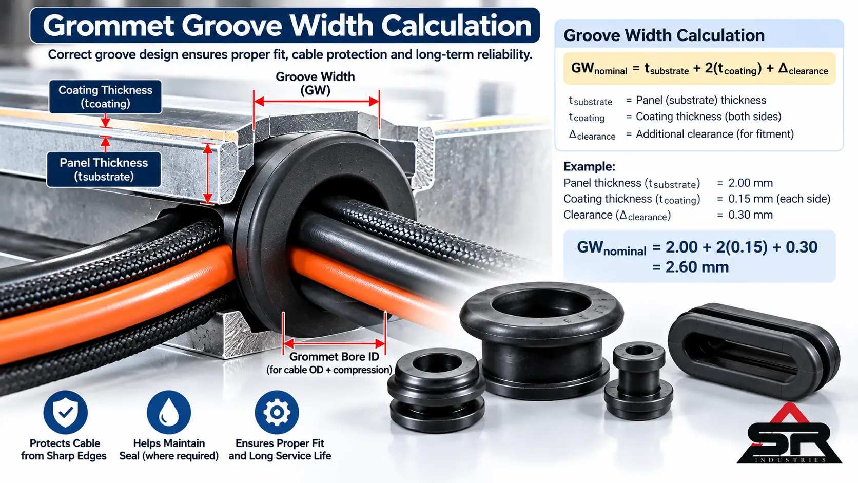
Groove width
A useful sizing relationship is:
Grommet Groove Width Sizing Formula
where t_substrate is the bare panel thickness, t_coating is the coating thickness per side and Δ_clearance is a design allowance. Δ_clearance can be positive, zero or negative depending on how the grommet is meant to work. In a lip-sealed design, flexible lips on the flange faces provide sealing and the groove mainly locates the part, so a small positive clearance can ease insertion. In a groove-sealed design, the panel edge is gripped by the groove to form the seal, so zero or negative clearance may be chosen and then proven by insertion and pull-out testing.
Illustrative calculation — not a universal design rule.
Take a 2.00 mm steel panel with a nominal powder coat of 0.09 mm per side, and a lip-sealed grommet using an assumed Δ_clearance of +0.10 mm.
- Finished panel: 2.00 + 2 × 0.09 = 2.18 mm
- Groove width: 2.18 + 0.10 = 2.28 mm
Now repeat the check at the coating extremes. If the coating specification allows 0.06 to 0.12 mm per side, the finished panel ranges from 2.12 mm to 2.24 mm. A groove designed around bare 2.00 mm steel would face up to 0.24 mm of unplanned interference at the heavy end, enough on some designs to raise insertion force sharply, roll the sealing lip or tear the flange. The same arithmetic applies to any substrate and finish; the design value of Δ_clearance comes from prototype testing of the actual grommet, not from this example.
Cable bore and cable construction
The bore is sized from the real cable, including its tolerance. A grommet drawn around a nominal 8.0 mm cable must also work on the smallest and largest cables that will be delivered. Cable data sheets and incoming measurements across several lots give a more honest range than the nominal value.
Cable construction changes how the same bore behaves:
- PVC jackets are relatively soft thermoplastics that can creep under sustained pressure, particularly at elevated temperature. Plasticiser can also migrate between PVC and some elastomers.
- XLPE and other cross-linked polyolefin jackets resist heat deformation better than PVC, though they still respond to sustained load at temperature, and their smoother, stiffer surface can reduce grip.
- Silicone-jacketed cables are soft and conform readily, but the jacket can be less resistant to cutting and abrasion, so flash and edge quality become more critical.
- Braided or shielded cables have a less uniform outer surface and sometimes less uniform diameter; the braid can hold the bore open locally and create a leak path unless the design accounts for it.
Radial compression
The degree to which the bore squeezes the cable can be estimated as:
Cr = (OD_cable − ID_grommet) / OD_cable
Illustrative calculation — not a universal design rule. An 8.0 mm cable in a bore with a 7.0 mm effective inner diameter gives Cr = 1.0 / 8.0 = 12.5%. If the cable tolerance is ±0.2 mm, compression ranges from about 10.3% (7.8 mm cable) to about 14.6% (8.2 mm cable). With ±0.4 mm tolerance, the range widens to roughly 7.9% to 16.7%.
Some designers use a band of roughly 10–18% as a starting point for evaluating cable grommet bores. That band is a design-practice starting range, not a standard requirement, and the correct value depends on the compound’s modulus, the bore length and lip geometry, the jacket material, the temperature range and the sealing and retention targets.
The mechanisms at each end of the range are well understood even though the exact limits are application-specific:
- Too little compression gives low contact pressure. Initial sealing may pass, but compression set, low-temperature stiffening or a cable at the small end of its tolerance can remove the remaining margin. Low compression also means low grip, allowing the cable to piston through the bore under vibration.
- Too much compression raises insertion force, can deform or permanently neck a thermoplastic jacket, and increases the stress the elastomer must hold for its whole life. Higher sustained stress tends to accelerate stress relaxation, so contact pressure falls over time.
Retention and insertion force
A grommet that seals but pulls out during harness routing has failed. Insertion force depends on lead-in geometry, flange stiffness, hardness, groove fit and surface friction. Retention depends mainly on the trailing flange: its overlap beyond the hole, its thickness, its stiffness at the lowest service temperature, and the condition of the hole edge.
A retention target is best set from the actual loads the harness can apply at that point during assembly, service and vibration, with a safety margin agreed by the design team. Both forces should be measured on real coated panels at the temperature extremes, because elastomer stiffness changes considerably between cold and hot conditions.
Ingress sealing
IEC 60529 defines IP codes and their test conditions. For water, IPX6 uses powerful water jets from a 12.5 mm nozzle and IPX7 uses temporary immersion; the high-pressure, high-temperature spray designated IPX9K is defined in ISO 20653 for road vehicles. An IP code applies to the tested enclosure or assembly, not to a loose rubber part. A grommet catalogue listing “IP67” means little until the grommet, panel, hole condition, cable and installation method are defined and tested together.
Sealing should also be proven after ageing. A grommet that passes when new may leak after thermal cycling if compression set and stress relaxation reduce contact pressure, or if a groove sized on bare steel never achieved its intended fit in the first place.
Installation
The line process is part of the design. Hand insertion, tool-assisted insertion and robotic insertion each tolerate different forces. Lubricants, if used, must be approved for compatibility with both the elastomer and the cable jacket, and their effect on long-term retention checked. Split grommets fitted around terminated harnesses need their closure verified; a split that does not close fully is a leak path and a retention weakness.
Grommet sizing workflow
- Confirm substrate thickness, coating type and the coating’s minimum and maximum DFT per side.
- Calculate the finished panel thickness range.
- Specify hole diameter, hole-making method and maximum burr height.
- Choose lip-sealed or groove-sealed concept, then set groove width and Δ_clearance.
- Measure real cable OD across lots and record jacket material and construction.
- Set bore ID and calculate compression at the minimum and maximum cable OD.
- Size flanges and lead-in for the target insertion and retention forces.
- Mould prototypes in the intended compound.
- Test insertion and pull-out at temperature extremes on real coated panels.
- Test sealing on the assembly, before and after thermal and fluid ageing.
D-Rings and Harness Routing Engineering
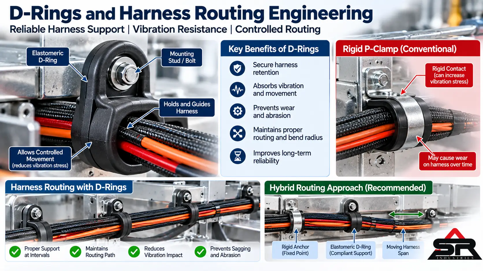
A rubber D-ring, often called a cable retention loop, supports a harness at a stud, weld nut or chassis tab while allowing a controlled amount of movement. It is not a sealing part. Its job is to locate the harness, keep it away from edges and hot surfaces, and manage how vibration and movement are transferred into the cable.
A rigid P-clamp, usually nylon or metal with a liner, does a related but different job: it fixes the harness positively at one point. Both are legitimate tools, and the choice depends on what the harness is doing at that location.
Why compliance matters on moving sections
Elastomers are viscoelastic. Under cyclic loading, part of the energy is stored and returned and part is dissipated as heat. That damping can reduce the vibration amplitude transferred into a harness compared with a very stiff support, and an elastomeric support can keep following a jacket that relaxes over time. The amount of damping depends heavily on compound, temperature and frequency, so it has to be checked rather than assumed.
A rigid clamp tightened on a thermoplastic jacket applies a fixed displacement. If the jacket creeps under that pressure at temperature, clamping force falls, and a loose rigid clamp can allow rattling against a hard edge. That does not make rigid clamps a poor choice; it means the clamp, liner and jacket combination needs to be validated for the temperature and time involved.
Harness resonance deserves attention in any routing design. A span between supports behaves somewhat like a beam; if excitation reaches its natural frequency, the bundle can whip and load the nearest connector. Terminal fretting, the micro-motion at a contact interface that raises contact resistance over time, is a known cause of intermittent faults and is sometimes a routing problem as much as a connector problem.
D-ring vs rigid clamp: decision matrix
| Consideration | Elastomeric D-ring tends to suit… | Rigid clamp tends to suit… |
|---|---|---|
| Static anchoring | Light harnesses where some compliance is acceptable | Defined anchor points that fix harness geometry |
| Dynamic routing | Sections across hinges, mounts or moving mechanisms | Sections that must not move at all |
| Vibration | Situations where damping and compliance help protect the harness | Situations where positive location matters more than damping |
| Jacket pressure | Distributing load over a wider contact area | Applications where the liner and clamp size control pressure well |
| Creep over time | Compounds with good compression set at service temperature | Jacket and clamp materials validated for creep at temperature |
| Temperature | Compound-dependent; EPDM, silicone and FKM cover different ranges | Material-dependent; heat-stabilised polyamides and metals cover different ranges |
| Installation | Loop-and-fasten or push-on designs | Fast, positive single-fastener installation |
| Serviceability | Easy harness release in many designs | Often straightforward, depends on fastener access |
| Cost | Generally a moulded part plus fastener | Often a low-cost standard part |
| Packaging space | Needs room for loop deflection | Compact |
Why hybrid routing is common
Many robust layouts use rigid clamps at defined anchor points and elastomeric supports on the spans between them. The anchors fix the harness geometry and protect connectors from routing loads; the compliant supports handle movement and vibration in between. The balance between the two comes from the movement envelope, vibration profile and packaging, and it is confirmed by testing the routed harness.
D-ring geometry
The loop should avoid sharp internal corners and abrupt changes in section where it flexes, because those features concentrate strain. A generous radius, for example around 3 mm on some loop designs, is an illustration of the principle rather than a figure to copy; the right radius depends on loop size, compound and movement. The bore should hold the harness without pinching it, and the mounting eye needs enough material around the fastener to resist tearing under stud load and vibration.
Cable Separators
A cable separator is a moulded part that keeps cables, conductors or bundles in controlled positions. In low-voltage routing its jobs are mostly mechanical: preventing cable-to-cable rubbing, keeping a predictable layout for assembly and service, and holding cables away from heat sources and moving parts.
Specification points include the cable diameters and tolerances it must accept, the retention force needed to stop cables sliding, the temperature range, fluid exposure and compatibility with the jacket materials it contacts. A separator that is too tight can deform thermoplastic jackets over time; one that is too loose lets cables migrate and rub.
When a separator sits between conductors at different potentials, it becomes part of an insulation system and must be treated with the same rigour described for battery separators below.
Battery Cell Separators
A battery cell separator can be asked to do several different jobs. Treating them as one job is where designs go wrong. The battery architecture, cell format, voltage and applicable regulations determine which functions a particular separator actually needs.
Nine functions that must be considered separately
- Mechanical cell spacing. Holding cells at a defined pitch within the module. Verified by dimensional checks and stack-assembly trials.
- Cell swelling accommodation. Lithium-ion cells change thickness during charge and discharge and tend to grow further as they age. Pouch and prismatic formats are the most affected. The magnitude depends on chemistry, format, state-of-charge window, temperature and ageing, so it should come from the cell supplier’s data or direct measurement. A compliant separator must absorb that movement without losing its ability to hold the stack, which makes compression set and stress relaxation at pack temperature important compound properties.
- Anti-fretting protection. Preventing relative movement between adjacent cells from wearing through cell wraps or insulating films.
- Electrical insulation. Providing solid insulation between conductive parts where the design depends on it. Solid insulation is evaluated separately from surface distances.
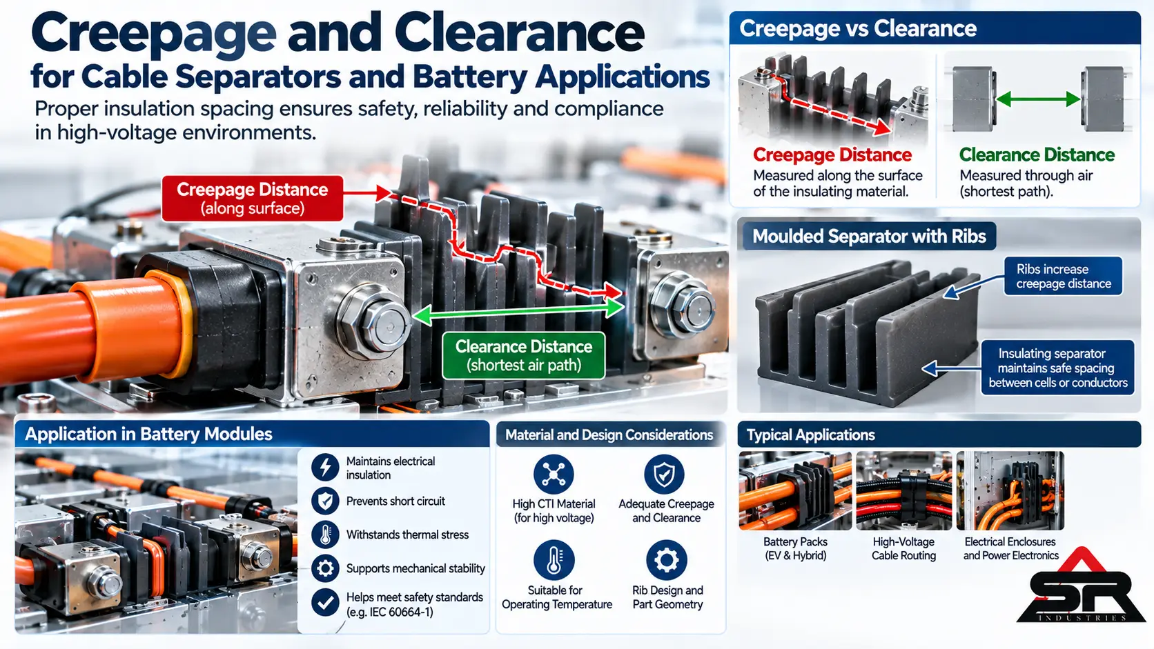
- Creepage. The shortest path along an insulating surface between conductive parts.
- Clearance. The shortest path through air between conductive parts.
- Tracking resistance. The ability of the insulating surface to resist forming conductive tracks under contamination and voltage stress, measured as CTI to IEC 60112.
- Flame performance. How the material behaves in a flammability test such as UL 94.
- Thermal barrier and propagation resistance. Slowing heat transfer between cells, and contributing to preventing a single-cell thermal runaway from spreading.
A single moulded separator may cover several of these, but no separator covers them automatically. Each function has its own requirement and its own evidence.
Creepage and clearance under IEC 60664-1
IEC 60664-1 sets out insulation coordination for equipment within low-voltage systems. Required creepage depends on working voltage, pollution degree and the material group of the insulating surface. Material groups are defined by CTI:
| Material group | CTI (IEC 60112) |
|---|---|
| I | 600 and above |
| II | 400 to below 600 |
| IIIa | 175 to below 400 |
| IIIb | 100 to below 175 |
Pollution degree describes the expected micro-environment. Pollution Degree 2 assumes normally non-conductive pollution with occasional temporary conductivity from condensation; Pollution Degree 3 assumes conductive pollution, or dry pollution that becomes conductive through expected condensation. The choice between them for a given location in a pack is an engineering judgment that needs to be justified, and it changes the required distances substantially.
As a published illustration, Infineon’s application note on insulation coordination for automotive power modules works through an 800 V working voltage at Pollution Degree 2 with a material group IIIa insulator and arrives at a minimum creepage of 8.0 mm for basic insulation. Moving to a material with a higher CTI group reduces the required creepage in the standard’s tables, which is one reason CTI matters when choosing a separator compound. Actual values must be taken from the current edition of IEC 60664-1, or from the product standard that applies to the equipment, for the specific insulation type (functional, basic, supplementary or reinforced).
Why ribs do not simply add distance. Ribs are a common way to lengthen a creepage path in a small space, but creepage cannot be read from rib height alone. IEC 60664-1 treats narrow grooves as bridged by contamination: a groove only contributes its full contour to the creepage path if its width reaches a minimum value “X”, which depends on pollution degree (0.25 mm for Pollution Degree 1, 1.0 mm for Pollution Degree 2 and 1.5 mm for Pollution Degree 3). A dense rib pattern with gaps narrower than X may add far less creepage than the drawing suggests. Rib pitch and gap width should be checked against X at the worst-case moulded tolerance.
Why dielectric strength is not a voltage rating. ASTM D149 measures dielectric breakdown voltage and dielectric strength of solid insulating materials under defined test conditions. The result is a material property. It does not account for contamination, moisture, surface tracking, temperature, ageing, mechanical movement or geometry. A statement such as “the compound has 20 kV/mm, so the separator is safe at 800 V” skips every factor that determines real performance. The insulation system is proven by dielectric withstand and insulation resistance tests on the assembly, and by compliance with the applicable standard.
Flammability, thermal barriers and thermal propagation are three different things
Flammability describes how a material burns in a defined test. A UL 94 V-0 classification, for example, reflects how quickly a vertical specimen self-extinguishes after a small flame is applied, with no flaming drips igniting cotton below. Whether V-0 or another class is required for a given separator depends on the customer and the applicable product or vehicle requirement.
Thermal barrier performance describes how well a layer slows heat transfer from a hot cell to its neighbour. Materials used for this include ceramifying silicones, which form a rigid char at high temperature, intumescent layers that expand when heated, and mineral-based sheets such as mica. Their performance depends on thickness, construction and the heat flux involved, and it is measured differently from flammability.
Thermal propagation resistance is a system-level outcome. In India, amendments to AIS-156 for L-category vehicles and AIS-038 Rev 2 for M and N categories introduced thermal propagation requirements: the battery system, or a representative subsystem including the cells and their connections, is tested to show that a single-cell thermal runaway does not lead to fire or explosion, and a warning of the thermal event is required. The same amendments also added provisions on cell-to-cell spacing. A separator material’s flame class contributes evidence but cannot, by itself, show that a pack meets this requirement.
Material Selection: EPDM, NBR, Silicone, FKM and TPV
Material selection starts from the exposure profile defined in steps 3 to 5 of the framework, not from habit. The notes below describe polymer families in general terms; the specific grade is what gets specified and approved.
EPDM
- Strengths: good resistance to weathering, ozone, water, steam and many glycol-based coolants; good low-temperature flexibility; peroxide-cured grades generally offer better heat ageing and compression set than sulfur-cured grades.
- Weaknesses: swells significantly in petroleum oils, fuels and many hydrocarbon solvents.
- Typical environments: outdoor panels, body and chassis pass-throughs away from oil, coolant zones, weather-exposed grommets and D-rings.
- Compatibility issues to check: mineral-oil based greases and assembly lubricants; plasticiser exchange with PVC jackets.
- When not to use it: where oil, fuel or hydrocarbon mist can reach the part.
NBR
- Strengths: resistance to many oils, fuels and greases, which improves with higher acrylonitrile (ACN) content.
- Weaknesses: weaker ozone and weathering resistance unless the compound is protected; higher ACN content reduces low-temperature flexibility; generally not chosen as an electrical insulator.
- Typical environments: engine-bay, gearbox and hydraulic-adjacent pass-throughs.
- Compatibility issues to check: specific fuels and additives, brake fluids (which many NBR grades do not tolerate), ozone exposure.
- When not to use it: outdoor exposure without ozone protection; electrical insulation duties.
Silicone and liquid silicone rubber (LSR)
- Strengths: a wide service temperature range at both ends; good electrical insulating properties in suitable grades; LSR moulds precisely and fills thin sections well, which helps fine rib geometry.
- Weaknesses: standard grades have modest tear and abrasion resistance; many grades swell in hydrocarbon oils and fuels.
- Typical environments: hot zones, high-temperature electrical parts, precision separators, thermal-barrier constructions using ceramifying grades.
- Compatibility issues to check: post-cure requirements for the specific grade, volatile content near sensitive contacts, abrasion at cable contact points.
- When not to use it: heavy abrasion or tearing loads without a high-tear grade; direct fuel or oil exposure.
FKM (fluoroelastomer)
- Strengths: high-temperature capability and resistance to fuels, oils and many aggressive chemicals.
- Weaknesses: higher cost; standard grades lose flexibility at low temperatures; some fluids such as certain amines, ketones and hot water or steam can be problematic depending on grade.
- Typical environments: hot, chemically aggressive zones where EPDM and NBR cannot survive.
- Compatibility issues to check: low-temperature requirement, specific fluid chemistry, tool corrosion during moulding.
- When not to use it: where a lower-cost compound meets the requirement, or where cold flexibility is critical and a low-temperature grade has not been validated.
TPE and TPV
- Strengths: thermoplastic processing, fast cycles, recyclable runners, and grades formulated for specific combinations of flame performance, hardness and appearance.
- Weaknesses: compression set and high-temperature performance are generally less favourable than well-formulated thermoset rubbers, varying widely by grade; long-term sealing needs careful validation.
- Typical environments: high-volume boots, covers, separators and less demanding sealing duties.
- Compatibility issues to check: fluid resistance of the specific grade, creep under sustained load at temperature.
- When not to use it: long-term static sealing at high temperature unless the grade has been proven for it.
Material-selection decision path
- Is oil, fuel or hydrocarbon exposure credible? If yes, EPDM is usually excluded; evaluate NBR, FKM or suitable specialty grades.
- What is the temperature range? Continuous exposure beyond the capability of EPDM or NBR grades points toward silicone or FKM; very low temperatures limit high-ACN NBR and standard FKM.
- Is outdoor, UV or ozone exposure present? Favours EPDM or silicone; NBR needs protection.
- Is the part part of an insulation system? If yes, require CTI, dielectric and volume-resistivity data for the exact grade; NBR is generally not suitable.
- Is long-term static sealing required? Weight compression set and stress relaxation at service temperature heavily; peroxide-cured EPDM, silicone and FKM grades are commonly evaluated.
- Is there high abrasion or tearing risk? Check tear strength (ASTM D624) and abrasion data; specify high-tear grades where needed.
- Is a flame classification required? Specify the test and class, not just “flame retardant”.
- Confirm compatibility with the cable jacket, lubricants and adjacent materials through contact ageing.
Why polymer family alone is insufficient
“EPDM” on a drawing is not a material specification. Two EPDM compounds can differ in polymer grade, filler type and loading, plasticiser type and content, cure system (sulfur or peroxide), antioxidants and other additives, and post-cure. Those differences change hardness, tensile and tear strength, compression set, fluid swell, electrical properties, flame behaviour and ageing. The same applies to every family. A complete material specification names the compound grade or a material standard callout, the hardness with tolerance, and the test requirements the compound must meet, and it states that changes to the compound require approval.
Hardness, Compression Set and Ageing
Shore A is not a durability score
Shore A hardness, measured under ASTM D2240, reports resistance to indentation by a specified indenter. It correlates loosely with stiffness, but it does not measure tear resistance, fatigue life, compression set, fluid resistance or ageing behaviour. A harder compound is not automatically more durable and a softer one does not automatically seal better.
Hardness interacts with geometry. A thin-walled grommet in a harder compound can be more compliant than a thick-walled grommet in a softer one. Insertion force, retention force, sealing contact pressure and cable jacket loading all depend on hardness and geometry together. Temperature also moves hardness: most elastomers stiffen noticeably at low temperature, which raises insertion force and reduces sealing compliance in cold conditions. Ageing can harden or soften a compound depending on its chemistry and the exposure.
Two compounds with identical Shore A values can behave very differently. Different fillers, polymers and crosslink densities produce different stress-strain curves above the small strains used in a hardness test, different compression set and different stress relaxation. For that reason, hardness is best specified as a nominal value with a tolerance (commonly ±5 Shore A points) alongside the other properties that matter for the function.
Starting points often evaluated in practice, such as softer compounds for easily inserted grommets and mid-range hardness for separators that must hold position, are reasonable hypotheses for a first prototype. The final value comes from testing the actual compound in the actual geometry.
Compression set and stress relaxation
ASTM D395 measures compression set: the permanent deformation remaining after a specimen is compressed for a defined time at a defined temperature and then released. Method B uses constant deflection and is widely used for sealing materials. The standard notes that the test is particularly applicable to service involving static compression.
Compression set results are only comparable when the test conditions match. A figure measured for 22 hours at 70 °C cannot be compared with one measured for 70 hours at 150 °C. Specifications should state the method, time, temperature and specimen type.
Stress relaxation, the gradual loss of sealing force under constant deflection, is closely related but not identical. For seals, it often describes long-term performance more directly than compression set does. Both are material-level evidence. Retained sealing of the actual grommet after thermal cycling and fluid exposure is the assembly-level evidence.
Fluid swell
ASTM D471 measures changes in mass, volume and properties after immersion in test liquids, including reference oils such as IRM 903. Results depend strongly on the fluid, temperature and duration. The fluids that actually reach the part, including coolants, fuels, cleaning agents and assembly lubricants, should be tested where they differ from the standard reference liquids.
Moulding Quality and Functional Defects
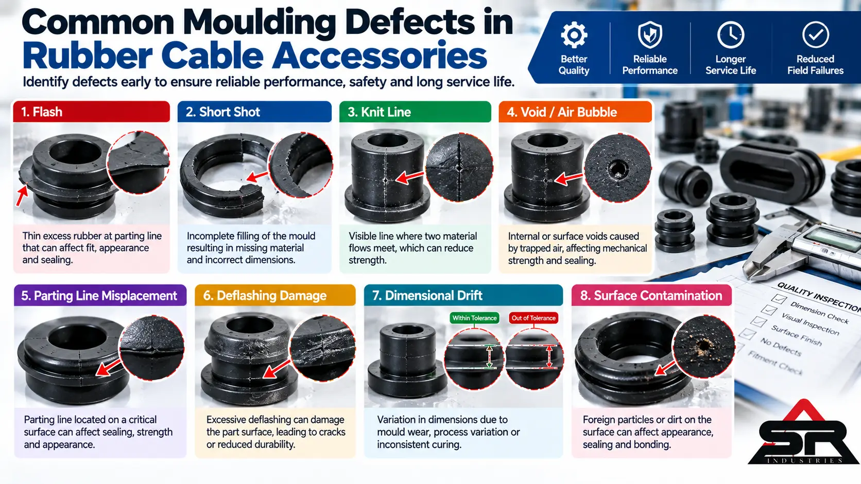
A moulded part can be made from the right compound and drawn correctly, then fail because of how it was moulded. Defects matter most when they sit on functional surfaces: cable-contact bores, sealing lips, flange faces and creepage ribs.
Flash is the classic example. A thin fin on a non-functional outer surface may never matter. The same fin inside a bore becomes a hard contact point that can abrade a cable jacket under vibration or hold a sealing surface open. Acceptance should therefore be zoned: tighter limits on functional surfaces, looser limits elsewhere, each written on the drawing. Some drawings specify very small maximum flash values, for example 0.02 mm, on critical bores; such a value is a drawing requirement for that part, not a general industry limit, and it must be measurable with the inspection method specified.
| Defect | Why it occurs | Why it matters | How to detect it | Corrective action |
|---|---|---|---|---|
| Short shot | Insufficient material, low injection pressure, poor venting, premature cure | Missing features, thin lips, weak flanges | Visual inspection, weight check, dimensional check | Adjust shot size and pressure, improve venting, review cure kinetics |
| Flash | Worn or damaged shut-offs, excessive pressure, insufficient clamp force, contamination on parting faces | Jacket abrasion, sealing interference, dimensional variation | Magnified visual inspection of functional zones; zoned acceptance criteria | Repair or re-fit shut-offs, clean tools, tune process, relocate parting line, appropriate deflashing |
| Knit line | Material fronts meeting and bonding poorly | Weak zones that can tear during installation or flexing | Visual inspection, tear or stretch testing at the knit location | Move gates, adjust flow and temperature, redesign flow path |
| Void / trapped air | Poor venting, moisture, volatiles, flow design | Weak sections, leak paths, reduced insulation integrity | Sectioning, density check, X-ray for critical parts | Add or clean vents, vacuum moulding, material drying, process adjustment |
| Mould contamination | Release agent build-up, compound residue, fouling | Surface defects, poor dimensions, inconsistent release | Visual inspection, tool inspection schedule | Defined tool cleaning intervals and methods |
| Dimensional drift | Tool wear, compound batch variation, process drift | Parts gradually move out of functional fit | Statistical process control on critical dimensions | Control limits, tool maintenance, incoming compound checks |
| Cavity-to-cavity variation | Unbalanced runners, uneven temperatures, differing wear | One cavity produces marginal parts | Measurement by cavity number; cavity identification on parts | Runner balancing, thermal balancing, cavity-specific maintenance |
| Cure variation | Inconsistent temperature or time, compound variation | Varying hardness, compression set and strength | Hardness checks, rheometer testing of compound, cure monitoring | Process control of time and temperature, compound acceptance testing |
| Post-cure variation | Inconsistent post-cure time, temperature, loading or airflow | Varying compression set and volatile content | Periodic property testing of post-cured parts | Controlled post-cure cycles and oven loading rules |
| Deflashing damage | Over-aggressive tumbling, wrong cryogenic temperature or media, excessive trimming | Nicks, rounded sealing edges, surface tears | Visual inspection of lips and edges after deflashing | Tune cycle time, media and temperature; protect critical features |
| Tool wear | Abrasive fillers, corrosive by-products, cycles | Flash growth and dimensional drift | Scheduled tool inspection, trend monitoring of flash and dimensions | Appropriate tool steels and coatings, refurbishment intervals |
| Parting-line misplacement | Design choice placing the split on a functional surface | Flash and mismatch exactly where they cause failure | Design review of tool layout | Move parting line to a non-functional surface at the design stage |
| Gate / runner imbalance | Runner design, gate size, cavity layout | Short shots, flash and variation between cavities | Cavity-by-cavity comparison; fill studies | Rebalance runners, adjust gates, flow simulation |
Tooling choices
Tool steel choice follows the compound, volume and surface-finish requirement. Hot-work steels such as H13 are widely used for rubber and LSR tooling because they hold hardness and stability through repeated thermal cycling. Corrosion-resistant mould steels, such as the stainless grade sold as S136, are often chosen where humidity, corrosive cure by-products (a known consideration with some FKM compounds) or high polish requirements make corrosion a risk. The exact steel, hardness and any plating or coating are decisions for the toolmaker based on the compound and expected tool life.
Multi-cavity tools benefit from runner systems that fill every cavity at similar pressure and temperature. LSR is commonly moulded with cold-runner systems that keep the material uncured until it enters the heated cavity. Parting lines are best placed on non-functional faces during tool design, when moving them costs little.
Cryogenic deflashing
Cryogenic deflashing cools parts, typically with liquid nitrogen, until thin flash becomes brittle while thicker sections stay more resilient, then removes the flash by tumbling or blasting with media. The effective process temperature depends on the compound’s glass transition temperature: silicone, for example, needs much colder conditions than most EPDM or NBR compounds. The process is useful for suitable parts, but it can also round sealing edges or damage thin lips if not tuned. Where it is used, the media, temperature, cycle time and post-process inspection should be defined in the control plan.
Specification mistakes that look acceptable on a drawing
- Groove width based on bare substrate when the panel is coated.
- Bore sized to nominal cable OD with no reference to the cable tolerance.
- “EPDM, 60 Shore A” with no compound grade, hardness tolerance or property requirements.
- “No flash” with no zones, measurement method or acceptance values.
- “IP67” on a component drawing with no assembly definition or test.
- “Flame retardant” with no test standard or classification.
- Creepage ribs drawn with gaps narrower than the X value for the intended pollution degree.
- Compression set specified without method, time and temperature.
- Hole diameter specified without burr height or punching direction.
Failure Analysis: Reading the Evidence
A failed moulded part is evidence. The damage location, its direction, what it touched and the conditions it saw usually narrow the cause quickly, provided the part is preserved before anyone cleans, cuts or replaces it.
Diagnostic sequence
- Observed failure. Record what failed and how it presented: leak, electrical fault, visible wear, cracking, swelling.
- Location. Is the damage at the parting line, panel edge, bend, retention point, near a connector, or at a sealing interface?
- Direction of damage. Axial wear suggests pistoning through a bore; circumferential or helical wear suggests rotation or vibration; one-sided wear points to a specific contact partner.
- Contact partner. What did the damaged surface touch: panel edge, flash fin, adjacent cable, fastener, cell surface?
- Movement. What vibration, articulation or handling did the location experience?
- Temperature. What were the continuous and peak temperatures, and did cycling occur?
- Fluid exposure. Which fluids could reach the part, in what concentration and for how long?
- Manufacturing feature. Does the damage align with a parting line, gate, knit line or deflashing mark?
- Material evidence. Hardness change, swelling, cracking pattern, surface chemistry; compare failed parts with unused parts from the same lot.
- Reproduction test. Recreate the suspected mechanism under controlled conditions.
- Root cause. Confirm the mechanism that reproduces the observed failure, then define corrective action.
Failure-mode diagnostic matrix
| Symptom | Likely mechanism | Possible root causes | Useful investigation tools | Typical corrective directions |
|---|---|---|---|---|
| Localised jacket wear inside a grommet bore | Abrasive fretting | Flash on bore, parting line on contact surface, excessive cable movement | Optical microscopy of bore and jacket, flash measurement, tool inspection | Relocate parting line, repair shut-offs, adjust deflashing, add retention |
| Jacket cut at panel entry | Edge contact | Burr on hole, grommet displaced or torn, undersized flange | Hole-edge inspection, fit check on real panel | Control burr and punching direction, redesign flange, review insertion |
| Water inside enclosure after thermal cycling | Loss of contact pressure | Groove sized on bare steel, low initial compression, compression set, stress relaxation | Coating thickness measurement, dimensional checks, sealing test after ageing | Resize groove to finished panel, adjust bore, review compound |
| Flange torn during assembly | Tear propagation | Excessive interference, burr, knit line at flange, low tear strength | Insertion-force measurement, cutout inspection, tear testing | Adjust lead-in or groove, control burr, move gate, higher-tear grade |
| Swollen, softened grommet | Fluid absorption | Fluid incompatible with compound | Identify fluid; immersion testing to ASTM D471 with the actual fluid | Compound change only after the fluid and conditions are confirmed |
| Hardened or cracked cable jacket next to a moulded part | Plasticiser migration, chemical attack, heat ageing | Incompatible compound-jacket pair, temperature beyond rating | FTIR on both materials, hardness comparison, contact ageing test | Compatible compound or jacket, add contact ageing to validation |
| Surface cracking on outdoor part | Ozone or UV attack | Compound without adequate ozone protection | Crack pattern inspection, ozone resistance testing | Ozone-resistant compound or protection |
| Carbonised path across an insulating surface | Surface tracking | Insufficient creepage, contamination, low CTI, rib gaps below X | CTI testing, rib geometry measurement, contamination analysis | Higher-CTI compound, revised ribs, review pollution degree assumption |
| Intermittent connector fault on a vibrating harness | Terminal fretting from harness motion | Resonant span, missing or rigid-only support | Vibration survey, contact-resistance monitoring | Revise support spacing, add compliant supports, keep rigid anchors near connectors |
What not to do
- Do not change EPDM to FKM just because a part swelled. First identify which fluid caused the swelling, its concentration, the temperature and duration, the actual compound grade involved, and whether the swelling came from the elastomer at all or from another material in contact with it. FKM is costly and has its own limitations; a better-matched EPDM grade, an NBR grade or removing the fluid source may be the correct answer.
- Do not raise hardness to fix a pull-out problem before checking groove fit, flange geometry and the panel hole. Harder compounds can raise insertion force and cause tearing instead.
- Do not clean the failed part before documenting deposits, discolouration and contact marks. Residues are often the key evidence.
- Do not test only new parts when the failure appeared after months in service. Age the parts first.
- Do not assume a moulding defect because the part is moulded. Panel edges, routing and cable tolerances cause many “grommet failures”.
Validation Testing
Validation should follow the evidence levels described in Section 1: material, component, assembly, and system where applicable. A test plan that stops at material data is incomplete.
| Level | Typical tests | Standards commonly referenced |
|---|---|---|
| Material | Hardness, tensile and elongation, tear strength, compression set, fluid swell, heat ageing, ozone resistance, CTI, dielectric strength, flammability | ASTM D2240, ASTM D412, ASTM D624, ASTM D395, ASTM D471, ASTM D573, IEC 60112, ASTM D149, UL 94 |
| Component | Dimensions, flash by zone, insertion force, pull-out force, retention after ageing | Drawing requirements, customer specifications |
| Assembly | Ingress protection, vibration and articulation durability, thermal cycling, insulation resistance, dielectric withstand | IEC 60529, ISO 20653, customer and OEM test specifications |
| System | Thermal propagation, vehicle-level durability, electrical safety approvals | AIS-156, AIS-038 Rev 2, applicable product standards |
Two rules keep a validation plan honest. First, test the assembly after environmental exposure, not only when new. Second, test the parts that will be supplied: production tooling, production compound, production process. Prototype results carry forward only as far as the prototype represents production.
For automotive programmes, the Production Part Approval Process (PPAP) defined by AIAG provides the framework for demonstrating that the supplier’s production process can make the part to specification. Submission Level 3, which requires the Part Submission Warrant with product samples and complete supporting data, is a common default, but the required level is set by the customer. Capability requirements for critical characteristics are also set by the customer; indices such as Cpk or Ppk at 1.33 or above are widely used thresholds, and the PPAP manual’s guidance for initial process studies refers to Ppk values above 1.67 as meeting acceptance criteria without further action.
RFQ and Supplier Specification
Most supplier problems start with an incomplete enquiry. An RFQ that describes the application, not just the shape, lets the supplier identify tooling risks, compound conflicts and unrealistic tolerances before steel is cut.
Mandatory RFQ inputs
- 2D drawing with critical-to-function dimensions identified
- 3D CAD model in a neutral or native format
- Prototype quantity and expected annual volume
- Material requirement: compound grade or material standard callout, hardness with tolerance
- Required quality documentation and PPAP level, where applicable
Recommended RFQ inputs
- Cable samples or cable data sheet with OD tolerance
- Panel samples or finished-panel specification including coating DFT range
- Photographs or CAD of the installation location
- Current part and failure history, if the part is a replacement
Application data
- Cable OD, tolerance, jacket material and construction
- Panel substrate, coating type and DFT range, hole-making method and burr limit
- Installation method: manual, tool-assisted or automated
- Movement and vibration profile
- Temperature range, continuous and peak
- Fluids, UV, ozone and contamination exposure
- Ingress requirement defined as an assembly test
- Working voltage, pollution degree and insulation type for electrical parts
Material data
- Compound grade or specification
- Hardness and tolerance
- Compression set requirement with method, time and temperature
- Fluid resistance requirements with test fluids and conditions
- Electrical requirements: CTI, dielectric strength, volume resistivity
- Flammability requirement with test standard and classification
- Colour and any marking
Quality documents
- Material certificates for each batch
- Dimensional reports by cavity
- Inspection plan and control plan
- Traceability requirements (batch, cavity, date)
- PPAP submission level where applicable
Validation requirements
- Which tests are carried out by the supplier and which by the customer
- Test standards and acceptance criteria for each
- Sample quantities and ageing conditions
Tooling requirements
- Number of cavities
- Parting-line restrictions on functional surfaces
- Flash acceptance by zone
- Deflashing method restrictions, if any
- Tool ownership, maintenance and marking
Change-control requirements
- Approval required before any change to compound, compound supplier, tooling, process or production location
- Notification period for changes
- Requalification requirements after approved changes
RFQ red flags
- “EPDM required” with no compound grade or property requirements
- “IP67 grommet” with no assembly definition, panel or cable data
- “70 Shore rubber” with no tolerance or test method
- “Flame retardant” with no test classification
- “High-voltage insulation” with no working voltage, pollution degree or insulation type
- “OEM quality” with no acceptance criteria
- “Same as sample” with no drawing, when the sample’s compound is unknown
Choosing the Right Component: Summary Decision Guide
- Cable passes through a panel or enclosure wall: start with a grommet. Decide early whether it must seal; if yes, plan an assembly-level ingress test.
- Harness needs support at a moving or vibrating section: evaluate an elastomeric D-ring or retention loop, alongside rigid anchors where the harness must be fixed.
- Harness must be fixed firmly at one point: a rigid clamp with a suitable liner is often the simplest answer.
- Cables must stay apart in a bundle or tray: use a cable separator; if the cables are at different potentials, treat it as part of the insulation system.
- Battery cells need spacing and breathing accommodation: use a cell separator, and list separately which of the nine functions in Section 6 it must perform and how each will be proven.
Engineering Sourcing Support from VIGA
Vinod Gautam Sales (VIGA) is a Delhi-based industrial products supplier. For engineering and procurement teams sourcing moulded cable accessories such as grommets, D-rings, retention loops and cable or cell separators, VIGA can receive the requirement and review it for feasibility and sourcing.
The review is most useful when the enquiry follows the RFQ structure in Section 12. Send the 2D drawing, 3D CAD, cable and panel dimensions including coating, the operating environment, any electrical requirements, and the quality documentation expected. Manufacturing route, material availability, test capability and documentation such as PPAP are confirmed against each specific requirement during the review rather than assumed in advance.
Frequently Asked Questions
How should a grommet be chosen for a cable pass-through?
Choose a grommet by defining the panel, cable and environment first. Confirm the finished panel thickness including coating, the hole size and edge condition, the cable diameter with tolerance, and whether sealing is required. Then select the compound for the temperature and fluid exposure, and prove insertion, retention and sealing on the real assembly.
How is grommet groove width calculated?
Groove width is calculated as substrate thickness plus coating thickness on both faces plus a design clearance: GW = t_substrate + 2(t_coating) + Δ_clearance. For example, 2.00 mm steel with 0.09 mm coating per side gives a 2.18 mm finished panel. The clearance term depends on whether the grommet is lip-sealed or groove-sealed and must be confirmed by testing.
How much radial compression should a grommet bore apply to a cable?
There is no single correct value. Compression is estimated as (cable OD − bore ID) / cable OD, and some designers start evaluation around 10–18%. The right value depends on the compound, bore geometry, jacket material, cable tolerance, temperature and sealing target. Too little compression risks leaks and pull-through; too much raises insertion force and jacket deformation.
How should rubber hardness be chosen for a grommet or D-ring?
Choose hardness together with geometry, not on its own. Shore A hardness (ASTM D2240) measures indentation resistance, not durability. It interacts with wall thickness, flange design, insertion force, retention, sealing and temperature, and two compounds with the same hardness can behave differently. Specify hardness with a tolerance and confirm it by testing prototypes in the chosen compound.
Which is better for grommets: EPDM, NBR, silicone or FKM?
The environment decides. EPDM suits weathering, ozone, water and many coolants but swells in oils and fuels. NBR resists oils and fuels but needs ozone protection. Silicone covers wide temperature ranges and electrical duties but has modest tear resistance. FKM handles hot, aggressive chemicals at higher cost. The specific compound grade matters as much as the family.
How can cable chafing be prevented at panels and supports?
Prevent chafing by controlling every contact point. Deburr or laser-cut panel holes, size grommets to the finished coated panel, keep parting lines and flash off cable-contact surfaces, secure the harness so it cannot piston or rub, and support moving spans with suitable routing parts. Validate with vibration testing on the routed harness.
When should a D-ring be used instead of a P-clamp?
Use an elastomeric D-ring where the harness moves or vibrates and compliance helps protect it. Use a rigid P-clamp where the harness must be fixed at a defined point. Many designs combine both: rigid anchors near connectors and compliant supports along moving spans. The decision should be confirmed by testing the routed harness.
What causes rubber grommet failure?
Rubber grommet failures usually come from the interface rather than the rubber alone. Common causes include grooves sized on bare steel instead of coated panels, burred panel holes, flash on the cable bore, insufficient or excessive compression, fluid incompatibility, compression set after thermal cycling, and poor installation. Diagnosis should start from the damage location.
How should flash be specified on a moulded rubber part?
Specify flash by zone. Define tighter limits on functional surfaces such as cable bores, sealing lips and creepage ribs, and looser limits on non-functional surfaces. State the measurement method and acceptance values on the drawing, and keep parting lines off functional surfaces during tool design. A general "no flash" note cannot be inspected consistently.
How should battery cell separators be designed?
Design a cell separator by listing the functions it must perform: spacing, swelling accommodation, anti-fretting, insulation, creepage, clearance, tracking resistance, flame performance and thermal barrier duty. Each needs its own requirement and evidence. Creepage depends on working voltage, pollution degree and CTI under IEC 60664-1, and thermal propagation is proven only at pack or subsystem level.
What information should be sent to a moulding supplier?
Send the 2D drawing and 3D CAD, volumes, compound grade or material specification with hardness tolerance, cable and panel data including coating, installation method, temperature and fluid exposure, electrical requirements, validation tests, quality documents such as PPAP level, and change-control expectations. Complete information lets the supplier flag tooling and material risks before quoting.
What tests should be included in validation of moulded cable accessories?
Include tests at every evidence level. Material tests cover hardness, compression set, fluid swell, tear strength and, for electrical parts, CTI and dielectric strength. Component tests cover dimensions, flash, insertion and pull-out force. Assembly tests cover ingress, vibration, thermal cycling and insulation performance. Battery parts may also need system-level thermal propagation evidence.
Engineering Consultation & Quotation
Rubber components are specified in minutes and relied on for years. For custom rubber moulded components within ASR Industries' published range, sharing the drawing or sample, material requirement, operating conditions and expected annual volume through the contact page allows material and process feasibility to be reviewed before a quotation is issued.