
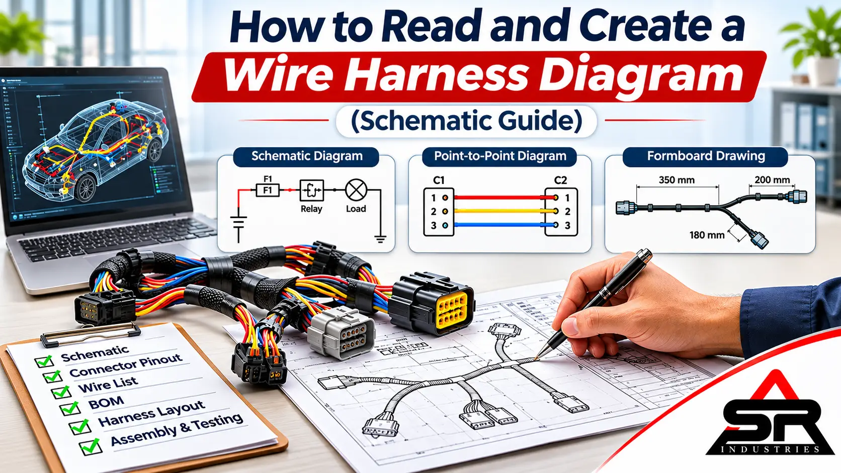
How to Read and Create a Wire Harness Diagram
A harness diagram is the single document that decides whether the build matches the design. Misread one symbol and the whole assembly is wrong. The cutting machine takes its wire lengths from the wire harness diagram, the operator takes cavity positions from it, and the test board takes its definition of a pass from it. This guide walks through how to read wire harness diagram sheets in the order a working harness engineer reads them, where a wiring harness schematic stops and a point-to-point drawing takes over, and how a complete harness drawing pack is created from a blank sheet, starting at load calculation and ending at the formboard.
Why the Harness Diagram Is the Master Document
Ask an operator on a harness line why wire 14 goes into cavity 3 and the answer is short: the drawing says so.
Unlike a printed circuit board, which a machine can compare against its design data, a harness is a bundle of flexible wires assembled largely by hand, and nothing about its shape reveals whether wire 14 belongs in cavity 3 or cavity 4. The drawing is the only reference. That is why harness plants treat a released drawing as a controlled document with a revision level, and why a harness built to an outdated revision is logged as a nonconformance even when it happens to work.
A complete drawing pack normally carries six things:
- Schematic – the electrical logic: which component connects to which, and through what fuse, switch or relay.
- Connector views and pinout tables – a face view of every connector with its cavity assignments.
- Wire list – every wire as a from-to record with size, colour and insulation type.
- Bill of materials – housings, terminals, seals, wire, tape, tubing, clips and labels, with part numbers and quantities.
- Harness layout or formboard drawing – the physical shape, with branch lengths and tolerances.
- Notes – applicable standards, crimp and test requirements, labelling and packing instructions.
Each reader pulls something different from the pack. A design engineer checks circuit function. A process engineer extracts cut lengths and crimp data. An assembly operator follows the formboard and connector views. A test engineer builds the continuity programme from the wire list. A service technician, years later, uses the schematic to trace a fault. One document set serves all five, which is why contradictions between sheets do so much damage: each reader trusts a different page.
Why it carries so much weight: Every downstream output is derived from the harness drawing: the bill of materials, wire cutting data, crimp specifications, formboard layout and electrical test programme. Under IPC/WHMA-A-620, the customer’s engineering documentation takes precedence over the standard itself, so an error on the drawing is built into every unit.
For automotive programmes run under IATF 16949, a drawing change has to pass through formal engineering change control before it reaches the shop floor. A pencilled correction on a printed formboard bypasses that control and leaves the plant running a second, undocumented design. How that change control works on a harness line is covered in the guide to IATF 16949 compliance in wire harness manufacturing .
Types of Harness Drawings (Schematic vs Point-to-Point)
A wiring harness schematic shows how circuits function, with components drawn as symbols and no regard for physical position. A point-to-point drawing shows each individual wire running from one connector cavity to another. Engineers use the first to understand circuit behaviour and the second to find where a wire physically ends.
Four drawing types turn up in harness work. They are often confused because all four get called “the wiring diagram” on the shop floor.
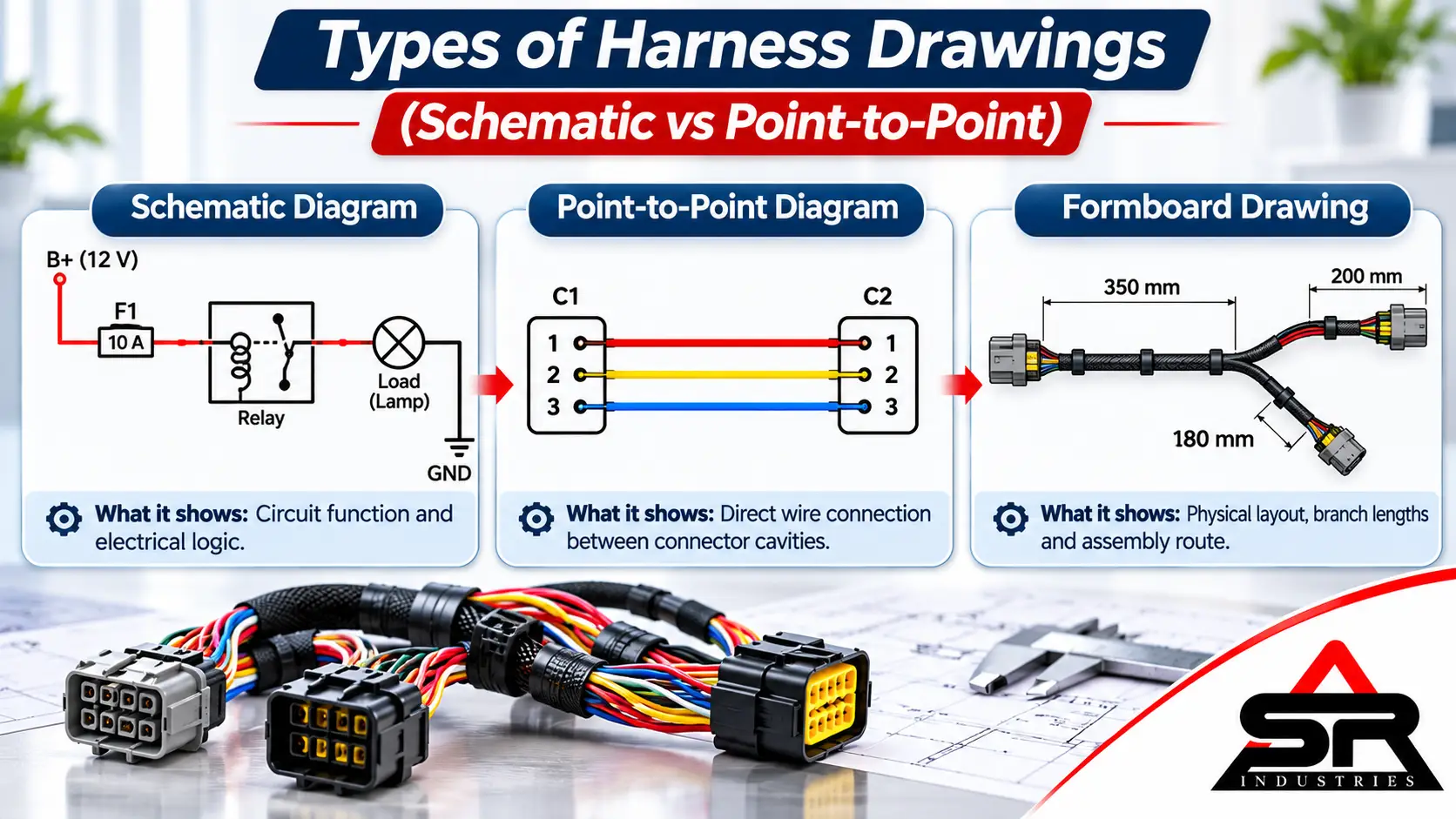
Schematic Diagram
The schematic is the functional view. Power sources sit at the top or left, loads in the middle and grounds at the bottom, with wires drawn as straight lines and right-angle turns. Distance on a schematic means nothing: two components drawn side by side may sit three metres apart in the vehicle. Schematics are used for circuit design, fuse and wire sizing, and fault diagnosis.
Point-to-Point Wiring Diagram
A point-to-point diagram drops the circuit logic and shows connectivity only. Each connector appears as a block with numbered cavities, and each wire is drawn from one cavity to its destination cavity, splice or terminal. It is the easiest drawing to build a small harness from, and for simple cable assemblies it often replaces the schematic altogether. Its weakness shows on large harnesses, where two hundred crossing lines become unreadable and a tabular wire list does the same job better.
Harness Assembly Drawing
The assembly drawing shows the harness as a physical object: main trunk, breakouts, branch lengths, connector orientation, coverings and clip positions. It is usually drawn to a reduced scale and carries the dimensions and tolerances the finished harness is inspected against.
Formboard Drawing
The formboard drawing is the assembly drawing reproduced at full scale for production. It has its own section further down.
The point-to-point vs schematic question is settled by the job in hand, as the comparison shows.
Wire Harness Drawing Types at a Glance
How each drawing type differs in scope, omitted details, and shop-floor audience.
| Drawing type | What it shows | What it leaves out | Main reader |
|---|---|---|---|
| Schematic | Circuit function, components, fuses, grounds | Lengths, routing, physical position | Design and service engineers |
| Point-to-point | Cavity-to-cavity wire connections | Circuit logic, lengths | Assemblers and technicians |
| Harness assembly drawing | Branch lengths, breakouts, coverings, tolerances | Circuit logic | Process and quality engineers |
| Formboard drawing | Full-scale build layout with fixture positions | Circuit logic | Assembly operators |
On most programmes the schematic and the layout are produced by different people, sometimes in different companies. The wire list is the bridge between them, and it is the first place to look when the two disagree.
Common Symbols & Notation
Most drawing misreads on a harness line trace back to one of two things: a symbol from an unfamiliar standard, or a colour abbreviation read in the wrong language.
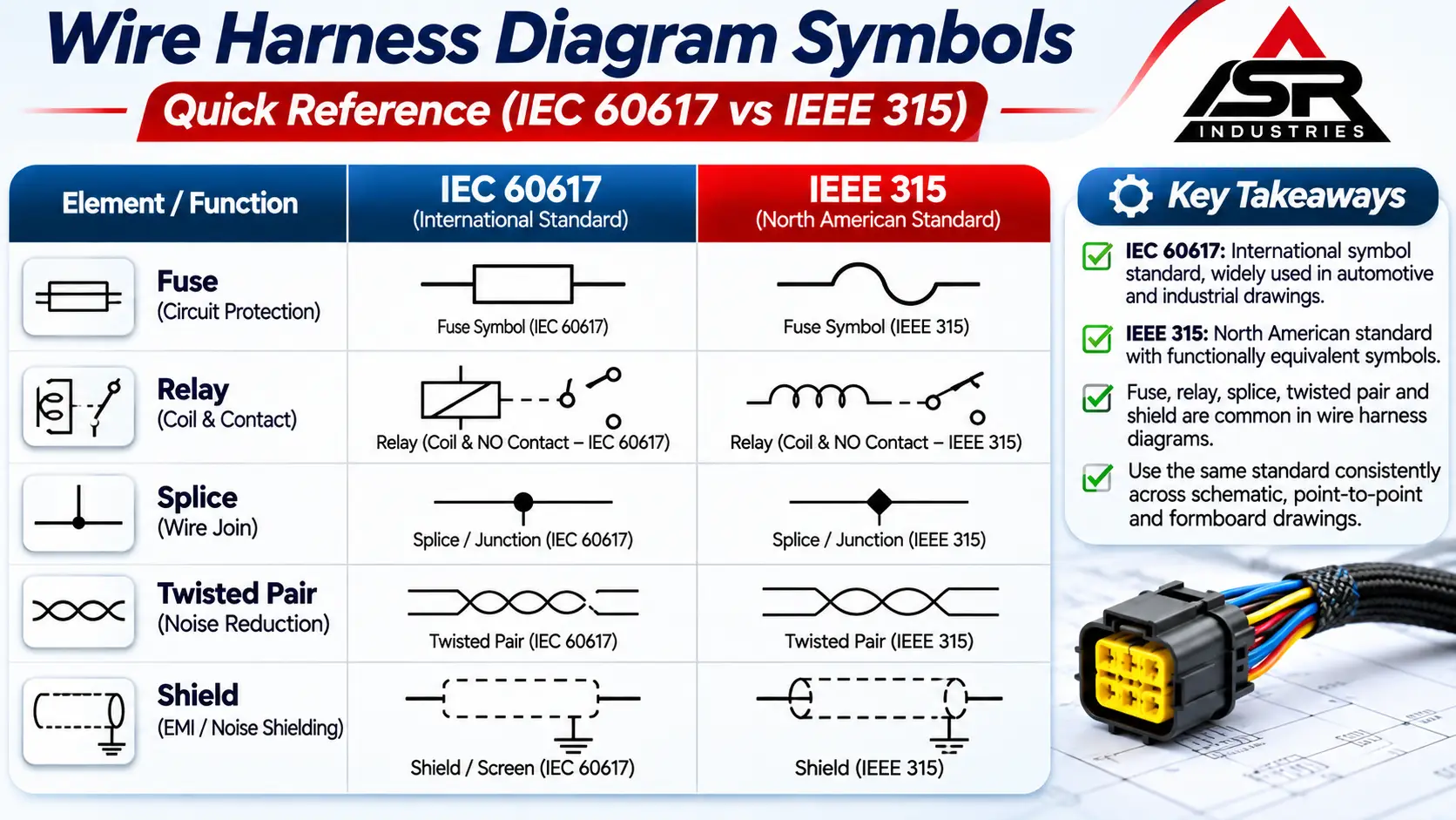
Two symbol families dominate. Drawings of European and Indian origin generally follow IEC 60617. Drawings of North American origin lean on IEEE 315. The differences are small but real: a fuse is a plain rectangle with a line through it in one system and an S-shaped curve in the other, and resistors, grounds and relay coils differ in similar ways. The legend on sheet one settles which family applies.
Wire callouts. Every wire carries an identifier and a short description. Metric drawings state conductor cross-section in mm² (0.35, 0.5, 0.75, 1.0, 1.5, 2.5 and upward). North American drawings use AWG, where a larger number means a thinner wire. The two scales have no clean one-to-one mapping. 0.75 mm² sits close to 18 AWG without being the same conductor, so crimp settings validated on one should be re-validated before they are used on the other.
Reading a wire callout: Harness wiring diagram symbols follow IEC 60617 or IEEE 315 for components, then add notation for wire size, colour, connector cavities and splices. A callout such as “0.75 RD/WH” means a 0.75 mm² conductor with red insulation and a white tracer. The legend on the drawing always overrides general convention.
Colour codes. IEC 60757 gives the two-letter codes seen on most modern drawings: BK black, BN brown, RD red, OG orange, YE yellow, GN green, BU blue, VT violet, GY grey, WH white, PK pink and TQ turquoise. A two-colour wire is written base colour first and tracer second, so BU/WH is blue with a white stripe. Older German-origin drawings use sw, br, rt, ge, gn, bl, gr and ws. Japanese-origin drawings use single letters, where B is black and L is blue. This is where mistakes creep in: “gr” is grey on a German legend and looks like green to an English reader, and “B” is black on one drawing and assumed to be blue on another.
A colour code should never be guessed.
Reference designators. Connectors typically carry an X, J, P or C prefix; splices S or SP; fuses F; relays K; ground points G. Cavities are written after a hyphen or colon, so X3-4 is cavity 4 of connector X3.
Automotive terminal numbers. Vehicle schematics based on DIN 72552 label circuits by function: 30 is permanent battery positive, 15 is ignition-switched positive, 31 is ground, and 85, 86 and 87 identify relay coil and contact terminals.
Line conventions. A dot where lines meet is a connection, while lines that cross without one simply pass over each other. A dashed outline around a group of conductors marks a shield or a multicore cable. A small loop drawn across two wires marks a twisted pair. An arrow or flag at the edge of a sheet points to the sheet and zone where the wire continues.
How to Read a Wire Harness Diagram in Order
A consistent reading order prevents most errors. Experienced harness engineers rarely start with the wires.
- Start with the title block. Confirm the part number, revision, units, scale and general tolerances. Read every note before reading any line.
- Find the legend. Identify the symbol standard, the colour code system and the wire size units.
- Locate the connectors. List every reference designator and note which are inline, which mate to devices and which are ring or spade terminals.
- Trace one circuit completely. Follow it from the power source through protection and switching to the load and back to ground. Then move to the next.
- Check each wire against the wire list. ID, size, colour and both end points should match the schematic exactly.
- Open the connector views. Confirm the view direction before assigning any cavity.
- Finish with the layout. Branch lengths, breakout positions, coverings and clip orientation come last, once the electrical content is understood.
Reading a Connector Pinout
A harness can pass every visual check and still reach the test board with half its circuits crossed. The usual cause is a connector view read from the wrong side.
The view direction matters more than anything else on the sheet. Looking at a connector from the mating face and from the wire-entry side gives mirror images: cavity 1 at top left in one view is at top right in the other. A good drawing states “view from wire-entry side” or “view from mating face” beside every connector outline. Where that note is missing, the right move is to stop and ask. Assemblers work from the wire-entry side, because that is where terminals are inserted, while test fixtures and mating components see the opposite face.
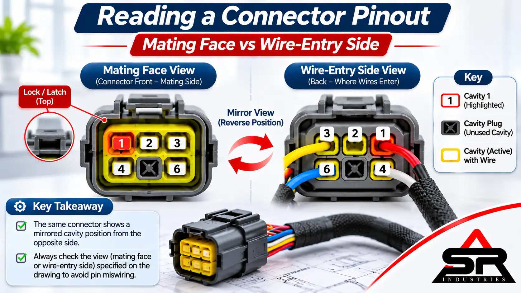
Cavity numbers are usually moulded into the housing, often only at the corner cavities or row ends on small-pitch connectors. Those physical markings are the reference, and the drawing has to agree with them.
What a pinout fixes: A connector pinout assigns each numbered cavity to one wire, terminal and signal, using a face view and a table. Reading it starts with the view direction, mating face or wire-entry side, followed by matching the cavity numbers moulded into the housing against the table. A mirrored view is the most common pinout error.
A few more points decide whether a pinout is read correctly:
- Gender is defined by the terminal on many drawings. A housing that looks like a plug may carry socket terminals, so the part number is the only safe reference.
- Terminal and seal part numbers vary with wire size. A 0.5 mm² signal wire and a 2.5 mm² power wire in the same sealed connector commonly need different terminals and different seals. The pinout table should list both for every cavity.
- Empty cavities still need a part. In a sealed connector an unused cavity takes a cavity plug. Leave it open and the sealing of the whole connector is compromised.
- Secondary locks are part of the build. TPA (terminal position assurance) and CPA (connector position assurance) parts appear on the bill of materials and must be fitted and locked at final assembly.
Below is a representative pinout for a six-way sealed automotive connector (X1), viewed from the wire-entry side:
Connector X1 Pinout Table (Wire-Entry View)
Cavity-by-cavity wire assignments, cross-sections, colour codes, and destinations for a 6-way sealed connector.
| Cavity | Wire ID | Size (mm²) | Colour | Signal | Destination |
|---|---|---|---|---|---|
| 1 | W101 | 1.5 | RD | Battery positive (terminal 30) | F1-1 |
| 2 | W102 | 0.75 | BK/YE | Ignition feed (terminal 15) | X3-4 |
| 3 | W103 | 0.5 | GN/WH | CAN high | X2-1 |
| 4 | W104 | 0.5 | GN | CAN low | X2-2 |
| 5 | Not used | – | – | – | Cavity plug |
| 6 | W105 | 1.5 | BN | Ground (terminal 31) | S1 |
Read row by row, the table says a good deal. Cavities 3 and 4 carry a CAN pair and must be twisted to the pitch given in the notes. Cavity 5 takes a plug. Cavity 6 runs to splice S1 instead of another connector, so at least two more wires share that ground.
The Wire List / Cut List
A wire list records every wire as a from-to connection with its ID, size, colour and type. A cut list adds the manufacturing data: cut length, strip length at each end, terminal and seal part numbers, and marking. Design intent lives in the wire list, and the cut list turns it into machine instructions.
On the wire list each wire occupies one row. A splice is treated as a destination in its own right: W105 runs from X1-6 to S1, and further wires run onward from S1. Two wires crimped into one terminal appear as two rows sharing a cavity, which tells the process engineer that the terminal must be rated for the combined cross-section.
The cut list is the wire list rewritten for the shop floor. The extract below continues the X1 example. In a production cut list, strip lengths are taken from the terminal manufacturer’s specification.
Wire Cutting & Stripping Schedule (X1 Extract)
Calculated cut lengths, end-to-end cavity routing, and strip dimensions for automated wire processing.
| Wire ID | Wire type | Size (mm²) | Colour | Cut length (mm) | From | Strip A (mm) | To | Strip B (mm) |
|---|---|---|---|---|---|---|---|---|
| W101 | FLRY-B | 1.5 | RD | 1,240 | X1-1 | 4.5 | F1-1 | 5.0 |
| W102 | FLRY-B | 0.75 | BK/YE | 860 | X1-2 | 4.0 | X3-4 | 4.0 |
| W103 | FLRY-B | 0.5 | GN/WH | 1,515 | X1-3 | 4.0 | X2-1 | 4.0 |
| W104 | FLRY-B | 0.5 | GN | 1,515 | X1-4 | 4.0 | X2-2 | 4.0 |
| W105 | FLRY-B | 1.5 | BN | 430 | X1-6 | 4.5 | S1 | 10.0 |
Cut length is a calculated figure. It is the sum of every trunk and branch segment the wire passes through on the layout, plus allowances for terminal insertion depth in the housing, for the path through each breakout and for splice overlap. Twisted pairs need a further allowance, because twisting shortens the pair. A wire cut to the bare drawing dimension nearly always ends up short, and Step 5 of the creation workflow below works through the arithmetic for W103.
On our automatic cutting and double-crimping lines at ASR Industries, we set the machine up directly from the cut list: wire type, length, strip lengths and the terminal for each end. The machine then delivers finished leads at line speed, and it reproduces a wrong entry just as faithfully as a right one. That is why our operators check a first-off sample against the list before a batch runs. Where cutting and crimping sit in the full build sequence is explained in the step-by-step guide to the wire harness manufacturing process.
Three checks catch most wire list problems before they reach production:
- Every wire ID on the schematic appears exactly once in the list.
- No connector cavity appears twice unless a double crimp is specified.
- The revision on the list matches the revision on the drawing.
How to Create a Wire Harness Diagram from Scratch
Reading starts at the title block and works inward. Creating starts with a list of electrical loads and a blank sheet, and the order of work matters, because every later step inherits the mistakes of the earlier ones.
The workflow at a glance: Creating a wire harness diagram takes five steps: calculate loads and size each wire, select connectors with their terminals and seals, draft the schematic with reference designators, build the pinout tables and from-to wire list, then calculate true cut lengths. The formboard drawing follows once those five are frozen.
Step 1: Define System Architecture and Load Calculations
Start with a load table. For every device, record nominal voltage, continuous current, peak or inrush current and duty cycle. Then fix the architecture: which loads share a fuse, where each ground returns, which signals travel as twisted pairs and which need a shield. IPC-D-620 is the reference document for harness design requirements at this stage.
Each wire is then sized against three criteria, and the largest result wins.
- Continuous current. The conductor must carry its load without exceeding the insulation’s temperature rating, after derating for ambient temperature and for the number of loaded wires in the same bundle.
- Voltage drop. On 12 V systems this often governs before heating does. The drop along a conductor is ΔV = I × ρ × L ÷ A, where I is current in amperes, L is length in metres, A is cross-section in mm² and ρ for copper is roughly 0.018 Ω·mm²/m near room temperature.
- Mechanical strength. Very small cross-sections are fragile in handling and limit terminal choice, so most customer specifications set a minimum size regardless of current.
A worked case shows why the second criterion matters. A 10 A load fed through 3 m of 1.5 mm² wire, with a 3 m ground return of the same size, loses 10 × 0.018 × 6 ÷ 1.5 = 0.72 V across the loop, which is 6% of a 12 V supply. Thermally the 1.5 mm² wire is comfortable at 10 A, yet the load at the far end is being starved of voltage. Moving both wires to 2.5 mm² brings the loop drop down to about 0.43 V.
Environment decides the insulation. Thin-wall PVC types such as FLRY-B suit cabin and general body circuits in automotive work, while engine-bay and battery-adjacent zones usually call for a higher temperature class. Sizes are stated in mm² or AWG, one system per drawing, and the fuse for each circuit is chosen to protect the wire: above the continuous load current, below what the conductor can safely carry.
Step 2: Select Connectors, Terminals, Seals and Cavity Plugs
Device connectors are usually dictated by the device. Inline connectors are the designer’s choice, made on cavity count, current per cavity, sealing requirement, operating temperature and vibration.
Terminal selection is where most first-time designs go wrong. Each terminal part number covers a defined wire range, and it has two crimp zones to satisfy. The conductor crimp barrel is matched to cross-section. The insulation crimp barrel, or the seal grip on a sealed terminal, is matched to the insulation outside diameter. Thin-wall and thick-wall wires of identical cross-section have different outside diameters, so a terminal that suits one may grip the other badly.
Plating follows the circuit. Tin covers general power and signal work, silver suits high-current and high-temperature contacts, and gold is reserved for low-level signals. Mating halves should carry the same plating, since tin running against gold invites fretting corrosion.
Sealed connectors add two more line items: a single-wire seal sized to the insulation diameter for every populated cavity, and a cavity plug for every empty one. TPA and CPA locks complete the set. All of it goes on the bill of materials with manufacturer part numbers, and crimp height and pull-force requirements are taken from the terminal manufacturer’s specification.
Step 3: Draft the Logical Schematic and Reference Designators
With wires sized and connectors chosen, the schematic can be drawn. Choose IEC 60617 or IEEE 315 symbols, state the choice in the legend, and lay the sheet out in the direction current flows: power sources at the top or left, then protection (fuses), then switching (switches and relays), then loads, with grounds along the bottom.
Reference designators come next. Every connector, fuse, relay, splice and ground point gets a unique designator, and every wire gets a unique ID that will follow it through the pinout, the wire list and the cut list. On automotive sheets, DIN 72552 terminal numbers are added at this point.
Splice nodes deserve deliberate placement. A splice appears wherever several loads share a feed or a ground, and each one becomes a physical joint that must be positioned, dimensioned and sealed on the layout later. Keep the number of wires per splice within what the splicing process is validated for.
Finally, annotate each wire with size and colour. Keeping colours unique within any one connector makes both assembly and field service easier.
Step 4: Build the Pinout Tables and From-To Wire List
Each connector on the schematic now gets its pinout table: cavity, wire ID, size, colour, signal, destination, terminal part number and seal part number. Harness CAD tools generate these from the schematic. In a spreadsheet workflow they are typed by hand, which makes the cross-checks below mandatory.
- Zero duplicate cavities. No cavity may appear twice unless a validated double crimp is specified, with a terminal rated for the combined cross-section.
- Every cavity accounted for. Each one holds a wire or a cavity plug. A blank row is an unanswered question.
- Twisted pairs defined. CAN and other differential pairs sit in adjacent cavities, and the notes state the twist pitch and the maximum untwisted length at each connector. CAN specifications typically ask for 30 twists per metre or more; the exact figure belongs to the customer’s network specification.
- Shields terminated on paper. The drawing states whether each shield is grounded at one end or both, and how the drain wire is terminated.
The from-to wire list falls out of the pinout tables: one row per wire, splices entered as nodes. A quick integrity test is to count wire-end entries. Every wire ID should appear exactly twice across all pinout tables and splice nodes, once for each end.
Step 5: Calculate True Cut Lengths
The layout dimension between two connectors is measured between reference points, typically breakout centres and connector faces. The wire itself travels further. It continues past the connector face to the terminal seat, it takes the outside line around breakout bends, and its stripped ends sit inside crimp barrels or a splice.
A workable formula is:
Cut length = layout path + terminal insertion depth at each end + breakout bend allowance + splice overlap + twist take-up
- Layout path is the sum of every trunk and branch segment the wire passes through.
- Terminal insertion depth runs from the dimension reference face to the end of the conductor inside the terminal. The strip length is part of this figure, so it must be included when the allowance is worked out from the terminal drawing.
- Breakout bend allowance covers the extra travel of a wire on the outside of a bend where a branch leaves the trunk.
- Splice overlap applies to any end that terminates in a splice.
- Twist take-up applies to twisted pairs, because each wire follows a helix that is longer than the straight pair.
Take W103 from the cut list above. Its layout path from X1 to X2 is 1,450 mm. Insertion depth is 12 mm at each end, adding 24 mm. The wire passes two breakouts at 5 mm each, adding 10 mm. It is twisted with W104 over 1,400 mm, and at 40 twists per metre on a wire of about 1.6 mm outside diameter, helix geometry gives a take-up close to 2%, or 28 mm. The total is 1,512 mm, entered on the cut list as 1,515 mm.
Rounding goes upward, because a few surplus millimetres disappear into the bundle while a short wire is scrap. Take-up and bend allowances are then confirmed on the first-article build and corrected in the cut list.
How a Formboard Drawing Is Created
By the time the cut list exists, the electrical design is finished. The remaining question is physical: what shape the harness takes on the bench, and how an operator reproduces that shape several hundred times a shift.
A formboard drawing starts life in three dimensions and ends up flat. The sequence below is the one most harness design teams follow, whether the tool is a dedicated harness CAD package or a 2D drawing and a spreadsheet.
- Freeze the electrical content. The schematic, connector selection and wire list must be stable. Laying out a harness whose pinouts are still moving guarantees rework.
- Define the physical route. In a 3D CAD model, the harness is routed through the vehicle or equipment along its real path, with clip points and bend radii respected. Where no 3D model exists, the route is measured on a prototype, often with a sample harness or a length of cord.
- Mark the breakouts. Every point where a branch leaves the main trunk is fixed, and the trunk is divided into segments between those points.
- Flatten the route to 2D. The branches are unfolded onto a plane. Segment lengths are preserved exactly, while branch angles are chosen to suit the board and the operator’s reach, so only the lengths on a formboard can be read as true dimensions.
- Dimension and tolerance every segment. Each length runs between defined references: breakout centre to breakout centre, or breakout to a stated face of the connector. The reference face has to be named, because the distance between the wire-entry face and the mating face of a large connector can exceed the length tolerance. IPC/WHMA-A-620 includes default length tolerances for drawings that state none, but a harness that must fit a tight installation should carry its own.
- Add coverings and hardware. Tape (spot, spiral or full wrap), corrugated tubing, braided sleeving, heat-shrink, grommets, clips and labels are drawn at their start and stop positions. Clips need an orientation as well as a position, or the harness will not sit on its mounting points.
- Plot at 1:1 and build the board. The full-scale print is fixed to a board, and forks, pegs and connector holders are placed along the wire paths. Older boards used nails for this, hence the name nailboard.
- Prove it with a first article. The first harness off the board is measured, fitted to the real product and electrically tested. Corrections go into the drawing, which is then re-released, so the board and the released revision stay identical.
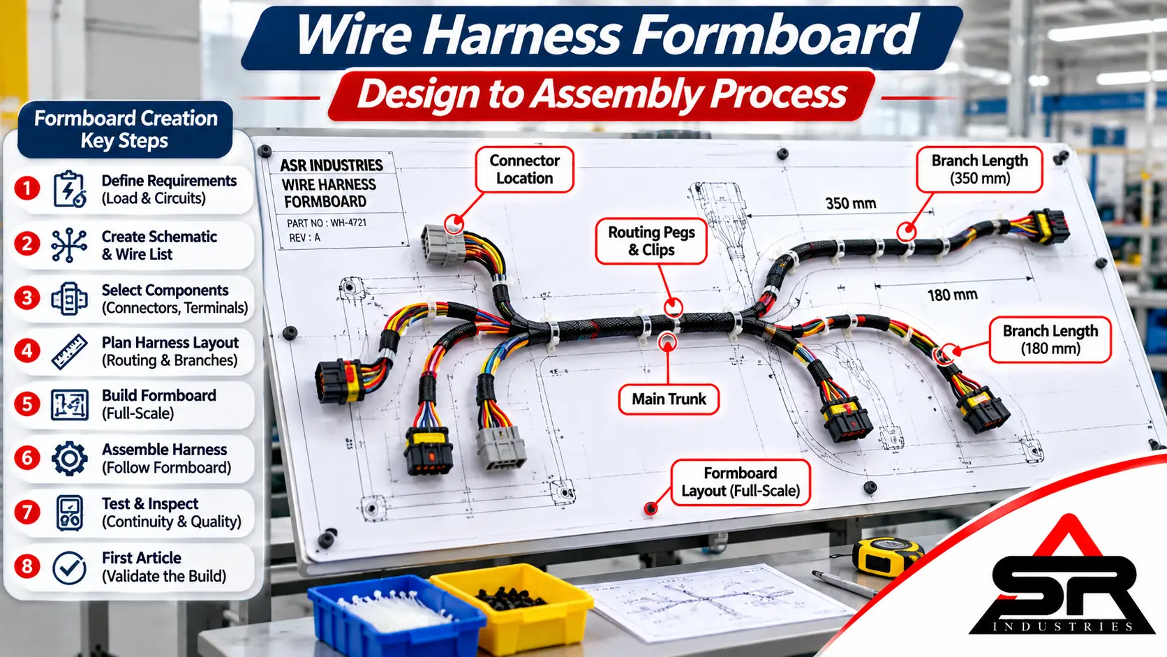
Formboard in short: Flattening the three-dimensional route of a harness into a full-scale two-dimensional layout produces the harness formboard drawing. Every trunk and branch is dimensioned, and connectors, coverings, clips and labels are added at their true positions. Printed at 1:1 and fixed to a board, it becomes the template operators build on.
Electrical test usually sits at the end of the same line. At ASR Industries, our test engineers verify finished harnesses on continuity and circuit test boards: the harness is plugged into mating connectors, and every wire is checked against the wire list for opens, shorts and crossed positions. When the test programme is generated from the same wire list as the cut list, the loop closes. What was designed, what was cut and what was tested are one data set.
Symbol Quick-Reference Table
This is the section to print and keep at the bench.
Most harness drawings rely on a small, repeatable set of symbols and callouts. The table lists the ones that appear most often on automotive, EV and industrial harness drawings, how each is drawn, what it means and the one detail worth verifying before the harness is built or quoted.
Wire Harness Symbols & Notation Quick-Reference
Standard schematic conventions, graphical appearances, meanings, and essential pre-build verification checks.
| Symbol or notation | How it appears | Meaning | What to verify |
|---|---|---|---|
| Wire | Solid line with ID and callout, e.g. W101 1.5 RD | Single insulated conductor | Size units (mm² or AWG) and colour legend |
| Junction | Solid dot where lines meet | Wires are electrically joined | Whether it is a splice or a shared terminal |
| Crossing | Lines cross with no dot | No connection | Nothing is joined by assumption |
| Splice | Dot or small ellipse labelled S1 or SP1 | Permanent joint inside the harness | Position dimension and sealing method |
| Twisted pair | Loop across two wires, or "TP" note | Two wires twisted together | Twist pitch in the notes |
| Shield | Dashed outline around conductors | Screened cable with drain or braid | Whether the shield is terminated at one end or both |
| Connector | Rectangle with numbered cavities, labelled X1, J1 or P1 | Multi-way connector | View direction and housing part number |
| Pin and socket | Arrow-shaped contact and forked contact | Male and female terminals | Terminal part number for each wire size |
| Cavity plug | Filled or crossed cavity in the connector view | Unused sealed cavity | Plug part number on the bill of materials |
| Ground | Stacked horizontal lines, or terminal 31 | Return path to chassis or battery negative | Ground point location and ring terminal stud size |
| Fuse | Rectangle with a line through it, or S-curve, labelled F1 | Overcurrent protection | Rating in amperes and fuse type |
| Relay | Coil box with a switch contact, terminals 85, 86, 30, 87 | Electrically operated switch | Coil voltage and contact rating |
| Ring terminal | Small circle at the wire end | Bolted or stud connection | Stud size and barrel size |
| Covering | Hatched band or note along a branch | Tape, tubing or sleeving | Start and stop dimensions and material |
| Off-sheet reference | Arrow or flag with sheet and zone | Wire continues elsewhere | Matching reference on the target sheet |
FAQ: Wire Harness Diagrams
What software is used to create wire harness diagrams?
Dedicated electrical CAD packages do most of this work, with Zuken E3.series, Siemens Capital, EPLAN Harness proD, SOLIDWORKS Electrical and AutoCAD Electrical among the common choices. Their advantage is that the schematic, wire list and formboard stay linked, so one change updates all three. Small harnesses are still drawn in general 2D CAD with a spreadsheet wire list, and automotive design data is commonly exchanged in KBL or VEC format.
What is a formboard in wire harness manufacturing?
It is the full-scale assembly board a harness is built on. A 1:1 print of the layout is fixed to the board, and forks, pegs and connector holders guide each wire along its path, which fixes branch lengths, breakout positions and connector orientation for every unit.
What is the difference between a wiring harness schematic and a wiring diagram?
Function versus connection. A schematic shows how the circuit works using symbols, with no reference to physical position or length, while a wiring diagram (also called a point-to-point diagram) shows the actual wire connections between connector cavities. Engineers design and diagnose from the schematic; assemblers and technicians build and repair from the wiring diagram and wire list.
How are wire colours shown on a harness diagram?
Each wire carries a colour abbreviation beside it, most often a two-letter IEC 60757 code such as RD for red, BK for black or BU for blue. Two-colour wires are written base colour first and tracer second, for example RD/WH. German and Japanese drawings use different abbreviations, so the legend on the drawing is the final authority.
Which standards apply to wire harness drawings?
Several, each covering a different layer. IEC 60617 and IEEE 315 define graphical symbols, IEC 60757 defines colour codes, DIN 72552 defines automotive terminal numbers, IPC-D-620 covers harness design requirements and IPC/WHMA-A-620 sets workmanship and acceptance criteria for the finished harness. Customer drawings and customer-specific standards take precedence over all of them, and the applicable revision should be stated in the drawing notes.
What should a harness drawing include before it is sent for a quotation?
A quotation moves fastest when the drawing pack contains:
- Schematic or from-to wire list
- Connector pinouts with housing, terminal and seal part numbers
- Wire types, sizes and colours
- Branch lengths with tolerances, and the reference face for each dimension
- Covering details: tape, tubing, sleeving, grommets and clips
- Electrical test requirements and applicable standards
- Annual volume, batch size and target start of production
Missing connector part numbers and missing tolerances are the two gaps that most commonly delay a quotation.
Share Your Drawing with ASR's Design Team
A harness drawing does not need to be finished to be useful. A schematic with connector part numbers, a marked-up sketch with branch lengths or a sample harness is usually enough for our design team to start a technical review.
At ASR Industries we manufacture wiring harnesses across five plants in India under IATF 16949:2016 and ISO 9001:2015, with in-house design and R&D teams, automatic wire processing and circuit test boards. Our engineers check the pack against the quotation checklist above, raise questions on anything missing or unclear, and come back with a quotation.
Send your drawing to ASR's design team through the contact page.
Still deciding whether the application needs a fully custom design? The comparison of custom vs standard wire harnesses is a sensible place to start.